
AG9900 SILVERTEL
Document overview
- Manufacturer or author: Provided By www.digicamel.com(FREE DATASHEET DOWNLOAD SITE)
- PDF pages: 21
Technical content
Features
IEEE802.3af compliant 1500V isolated DC/DC Converter Ultra Low Profile Tiny SMT (14mm x 21mm X 13mm) or DIL package (14mm x 21mm X 8mm) Low cost Input voltage range 36V to 57V Minimal external components required Short-circuit protection Industrial temperature option available Over temperature protection (Industrial Temperature version- MT or LP) Adjustable Output Silvertel “design-in” assistance
Description
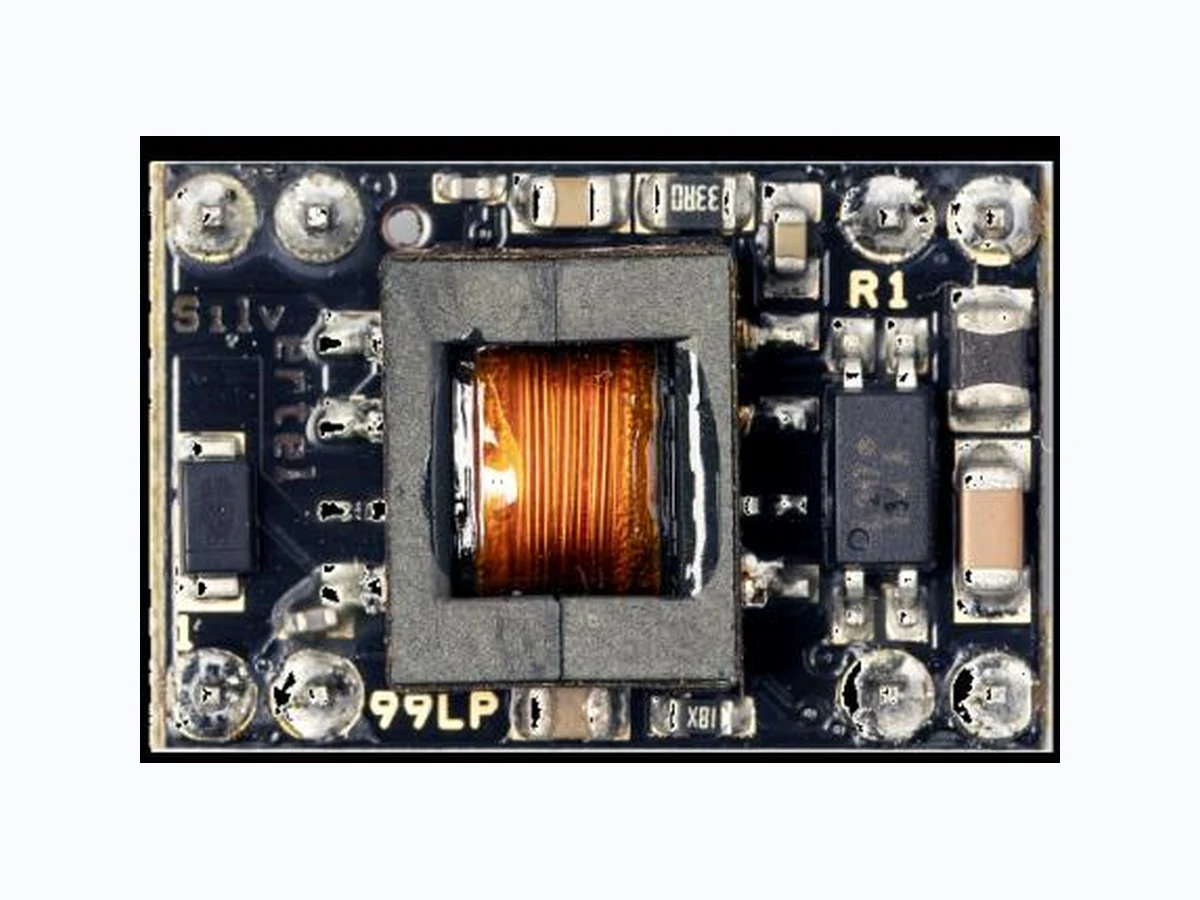
The Ag9900 Power-over-Ethernet (PoE) modules are the smallest POE solution in the world and designed to extract power from a conventional twisted pair Category 5 Ethernet cable, conforming to the IEEE 802.3af PoE standard. The Ag9900 signature and control circuit provides the PoE compatibility signature required by the Power Sourcing Equipment (PSE) before applying up to 15W power to the port. The Ag9900 provides a Class 0 signature. The DC/DC converter operates over a wide input voltage range and provides a regulated output. The DC/DC converter also has built-in short-circuit output protection.
V2.4 April 2020 Datasheet 3 © Silver Telecom 2020 Ag9900 Ultra Miniature PoE Module
1 Product Overview
Part Number1 Nominal Output Voltage Output Power2 Date code3 and Voltage Marking Ag9903M 3.3V 6 Watts 3 WWYY Ag9905M 5.0V 9 Watts 5 WWYY Ag9912M 12.0V 12 Watts 12 WWYY Ag9924M 24.0V 12 Watts 24 WWYY Industrial Temperature Part Number1 Nominal Output Voltage Output Power2 Date code3 and Voltage Marking Ag9903MT 3.3V 6 Watts 3T WWYY Ag9905MT 5.0V 9 Watts 5T WWYY Ag9912MT 12.0V 12 Watts 12T WWYY Ag9924MT 24.0V 12 Watts 24T WWYY Low Profile Part Number1 Nominal Output Voltage Output Power Date code3 and Voltage Marking 70˚C 85˚C Ag9903LP 3.3V 4.9 Watts 3.6 Watts 3 WWYY Ag9905LP 5.0V 7 Watts 4.5 Watts 5 WWYY Ag9912LP 12.0V 10 Watts 6 Watts 12 WWYY Note 1: The Ag9900 complies with the European Directive 2011/65/EU for the Restriction of use of certain Hazardous Substances (RoHS) including Directive 2015/863 published in 2015, amending Annex II of Directive 2011/65/EU. Moisture Sensitive Level 1 and HBM 1. Note 2: At 25°C with VIN = 48V Note 3: Date code format: “WW” = Week Number, “YY” = Year; if the industrial temperature version, Ag9900MT, is chosen it will be marked with the letter “T” after the voltage variant. Table 1: Ordering Information
V2.4 April 2020 Datasheet 5 © Silver Telecom 2020 Ag9900 Ultra Miniature PoE Module Pin Description Pin # Name Description +VDC DC Output This pin provides the regulated output from the DC/DC converter. 3 -VDC DC Return This pin is the return path for the +VDC output.
4 ADJ
Output Adjust The output voltage can be adjusted from its nominal value, by connecting an external resistor from this pin to either the +VDC pin or the - VDC pin. VIN+ Direct Input + This pin connects to the positive (+) output of the input bridge rectifiers. 6 VIN- Direct Input - This pin connects to the negative (-) output of the input bridge rectifiers. 8 Table 2: Pin Description
V2.4 April 2020 Datasheet 6 © Silver Telecom 2020 Ag9900 Ultra Miniature PoE Module
2 Functional Description
The Ag9900 requires minimal external components as shown in Figure 3. C1 must be fitted for output stability and should be a minimum of 100µF. This capacitor should be positioned as close to the output pins as possible. C1 is also required to handle load step change and reduce the output ripple. For applications where the output needs to cope with high load step changes, or to reduce the output ripple we recommend using a low ESR electrolytic as this reduces the output ripple. Also a low ESR capacitor is essential for operation below 0°C. BR1 and BR2 can be inexpensive bridge rectifiers, for example MB4S or MB6S. Figure 3: Typical Connection Diagram The output adjust input (ADJ) is optional, it is provided to give greater flexibility to the Ag9900 product range. Further information on using these inputs can be found in Section 2.3.1. The Ag9900 must always supply a minimum current; see Section 8.3 - Minimum Load for more information. When operated below this level the Ag9900 will emit a low level audible noise. The reason that the module emits this noise is due to the dc/dc converter running in discontinuous mode. Ag9900 RX TX VIN+ VIN- +VDC -VDC ADJ Output RJ-45 BR1 BR2 VB1 VB2 VA1 VA2 RB C1 = 100µF 25V C2 = 10uF 25V RB = ≥ I load min C1 C2
V2.4 April 2020 Datasheet 7 © Silver Telecom 2020 Ag9900 Ultra Miniature PoE Module If this audible noise is not an issue, then the Ag9900 can work safely with a much smaller load. But to ensure that the PSE has a sufficient load to meet its Maintain Power Signature (MPS), it would be advisable not to operate the Ag9900 below the specified minimum load. Input The Ag9900 is compatible with equipment that uses Alternative A (power on data pair) or Alternative B (power on spare pair) options, see Figure 4. It is specified that the PSE does not apply power to both outputs at the same time (Refer to IEEE802.3af for more information). Figure 4: Typical System Diagram PD Signature 2.2.1 When the Ag9900 is connected to the Cat5e cable, it will automatically present a Powered Device (PD) signature to the Power Sourcing Equipment (PSE) or Midspan Equipment, when requested. The equipment will then recognise that a powered device is connected to that line and supply power. Power Classification 2.2.2 The Ag9900 is set to Class 0 (0.44 Watts to 12.95 Watts) operation. Start-up Power 2.2.3 It is important that during start-up the Ag9900 input voltage is ≥42V, this will ensure that the module powers up correctly. Once the dc/dc converter is up and running the module will work normally even if the input voltage is reduced to its minimum level of 36V. When using an IEEE802.3af compliant PSE this will not be an issue, as the minimum output voltage of the PSE must be ≥44V. PSE (48V) Ag9900 DC OUTPUT VIN+ VIN- +/- +/- POWERED DEVICE (PD) POWER SOURCING EQUIPMENT (PSE) RX TX TX RX +VDC -VDC VA1 VA2 VB1 VB2
V2.4 April 2020 Datasheet 8 © Silver Telecom 2020 Ag9900 Ultra Miniature PoE Module Output The Ag9900’s DC/DC converter provides a regulated output that has built-in short-circuit output protection – refer to Table 1: Ordering Information for voltage and power ratings. Output Adjustment 2.3.1 The Ag9900 has an ADJ pin, which allows the output voltage to be increased or decreased from its nominal value. Figure 5 shows how the ADJ pin is connected. Figure 5: Output Adjustment Reducing the output voltage, connect R between ADJ and +VDC Value of R Ag9903 output Ag9905 output Ag9912 Output Ag9924 Output Open Circuit 3.30V 5.00V 12.00V 24.00V 0 Ohms 3.20V 4.48V 10.0V 19.85V Increasing the output voltage, connect R between ADJ and -VDC Value of R Ag9903 output Ag9905 output Ag9912 output Ag9924 Output Open Circuit 3.30V 5.00V 12.00V 24.00V 0 Ohms 3.78V 5.65V 12.75V 25.10V Table 3: Output Adjustment Resistor (R) Value Ag9900 +VDC -VDC ADJ Ag9900 +VDC -VDC ADJ Increasing the output voltage from nominal Reducing the output voltage from nominal R R
V2.4 April 2020 Datasheet 9 © Silver Telecom 2020 Ag9900 Ultra Miniature PoE Module Additional Output Filtering 2.3.2 The Ag9900 as shown in Figure 3 offers the minimum capacitance the customer must fit, however Figure 6 shows two cost effective methods for reducing the ripple and noise, if required. Figure 6: Output Filtering The simplest and cheapest solution is shown in Figure 6 - Output Filter A. Taking the Ag9912M as an example, this will reduce the ripple and noise to typically 120mVp-p at maximum load. Adding a PI filter, as shown in Figure 6 – Output Filter B, will take the ripple and noise level down further to typically 25mVp-p. Ag9900 +VDC -VDC Ag9900 +VDC -VDC Output Filter BOutput Filter A OutputOutput C1 = 100µF 25V C2 & C3 = 10µF 25V Ceramic C1 = 100µF 25V C2 & C3 = 10µF 25V Ceramic L1 = 1.8µH C3 C3C1
V2.4 April 2020 Datasheet 10 © Silver Telecom 2020 Ag9900 Ultra Miniature PoE Module
3 Protection
The Ag9900 must be protected from over-voltages exceeding the 80V maximum rated surge input voltage. An inexpensive but effective solution can be achieved by connecting a tranzorb diode across the input; see Figure 7. Figure 7: Ag9900 Input Protection More information is available is Apps Note “ANX-POE-Protection”. Thermal Protection The standard Ag9900M does not have built-in thermal protection. If this module is intended to be used in high ambient temperatures >50°C then we would recommend either the Industrial temperature version Ag9900MT or the Ag9900LP (both include thermal protection) to be used. The thermal protection reduces the output power, see Figure 8 through Figure 14, to ensure that the maximum component temperature is not exceeded. Full output power will be restored when the ambient temperature drops back down into the safe operating range. Ag9900 SMAJ58A VIN+ VIN-
V2.4 April 2020 Datasheet 11 © Silver Telecom 2020 Ag9900 Ultra Miniature PoE Module
4 Operating Temperature Range
Because the Ag9900 is a power component, it will generate heat, so it is important that this be taken into consideration at the design stage. The heart of the Ag9900 is a DC/DC converter, which like any other power supply will generate heat. The amount of heat generated by the module will depend on the load it is required to drive, and the input voltage supplied by the PSE. The information shown within this section of datasheet is referenced to a nominal 48Vdc input voltage supplied by the PSE. The Ag9900M has a maximum ambient operating temperature of 70˚C without any heat-sinking, while the Ag9900MT and Ag9900LP able to operate up to 85˚C while heatsinking to a host PCB; see below Figure 8 through Figure 14. These results were performed in an environment chamber - Associated Environmental System SD-302.The performance of the Ag9900M can be improved by forcing the airflow directly over the part, and by using a thermal pad such as Bergquist .1” Ultra soft gap pad or thermal paste such as thermally conductive Oxime Cure paste. The customers PCB can then be thermally mounted (using a Bergquist 0.1” Ultra soft gap pad) to the chassis of the host equipment by using the thermal relief pads (see Figure 15 and application note “ANX- POE-Thermal-Considerations” for more information). The output stage of the Ag9900M has no built-in thermal protection; however thermal protection is available with the Industrial temperature version Ag9900MT or Ag9900LP module. To prevent the module from being damaged it is recommended that the module be powered by an IEEE 802.3af compliant PSE or midspan equipment. However the Ag9900 may be powered by a user designed power supply which should include thermal and over current protection and be current limited to 400mA. Figure 8: Ag9924M Operating Profile -40 -10 0 10 20 30 40 50 60 70 Output Power (W) Ambient Temperature (°C) -30 -20 85 Ag9924M Ag9924MT
V2.4 April 2020 Datasheet 13 © Silver Telecom 2020 Ag9900 Ultra Miniature PoE Module Thermal Considerations Each application is different; therefore it is impossible to give fixed and absolute thermal recommendations. Due to the small size of this module, it is important that as much heat as possible is drawn away from it. It is also important that any enclosure has sufficient ventilation for the Ag9900 and a direct airflow if possible. One simple method for drawing some of the heat away from the Ag9900 is by means of power planes connected to the +VDC and -VDC pins of the Ag9900. This technique can be used to draw heat away from the DC/DC converter via the output pins. These power planes must be on the outer layers of the PCB and the best results are achieved by having power planes on both sides of the main board with multiple through- hole connections. An example of this is shown in Figure 15 with an Ag9900M module. Figure 15: Ag9900M Thermal Relief Power Plane +VDC - VDC Keep out area, ensure the output tracks have sufficient clearance from the module input tracks to maintain the 1500V isolation barrier. Heatpad Bottom side copper pour of customers PCB Copper pour with via holes connecting to bottom side of customers PCB
V2.4 April 2020 Datasheet 14 © Silver Telecom 2020 Ag9900 Ultra Miniature PoE Module A method that we would recommend when using the Ag9900 series is the use of a thermal gap pad or thermal paste, such as Berquist ultra soft 0.1in or Thermally conductive Oxime Cure paste, be placed underneath the Ag9900 PCB as shown below in Figure 16. The gap pad or paste must fully cover the components on the bottom side of the PCB to provide the best possible thermal conduction through the material to the customers PCB. Figure 16: Thermal Gap Pad Position It is important to remember that the ESR of the external electrolytic capacitors will increase considerably when the ambient temperature falls below 0°C. If the Ag9900 is going to be used in applications where the ambient temperature can fall below 0°C, selection of appropriate output filter components must be done at the design stage. Ag9900M Bottom Side Position of Gap Pad Gap Pad Or Thermally Conductive Oxime Cure paste Customers PCB Side View
V2.4 April 2020 Datasheet 15 © Silver Telecom 2020 Ag9900 Ultra Miniature PoE Module
5 Typical Application
The Ag9900 can be used in numerous applications. In the example shown in Figure 17, the data outputs from the switch are connected to the inputs of a midspan. The midspan will then add power (to the data) on each output that supports Power over Ethernet (PoE). In this example port 1 is connected to an Ethernet camera and port 2 is connected to a wireless access point, both of these devices have a built-in Ag9900. When the midspan is switched on (or when the device is connected), the midspan will check each output for a PoE signature. On ports 1 and 2 the Ag9900 will identify themselves as PoE enabled devices and the midspan will supply both data and power to these peripherals. The other ports (shown in this example) will not have a PoE signature and the midspan will only pass the data through to these peripherals. The midspan will continuously monitor each output to see if a PoE enabled device has been added or removed. Figure 17: Typical Application Ag9900M Ethernet Camera Wireless Access Point Midspan Equipment Switch Patch Cables PC's and other non PoE peripherals Ag9900M Silvertel
V2.4 April 2020 Datasheet 16 © Silver Telecom 2020 Ag9900 Ultra Miniature PoE Module
6 Isolation
To meet the safety isolation requirements of IEEE802.3af section 33.4.1 a Powered Device (PD) must pass the electrical strength test of IEC 60950 sub clause 6.2. This calls for either a) 1500Vac test or b) 1500Vdc impulse test. The Ag9900 is specified to meet the 1500Vdc impulse test. It is also important that the tracks on either side of the isolation barrier have at least a 3mm clearance, see Figure 10 & Figure 14 for more information. Layout Consideration Figure 18 shows the position of the isolation barrier, this area must be kept clear of tracks under the Ag9900 module. Figure 18: Layout Consideration Note: The keep out area is on the top layer of the mother-board under the module 3.00 3.00 6.27 11.03 5.08 Ag9900 Bottom side 11.3814.00 Keep out area 2.54
V2.4 April 2020 Datasheet 17 © Silver Telecom 2020 Ag9900 Ultra Miniature PoE Module
7 EMC
The Ag9900 uses a dc/dc converter with pulse width modulation, so care does need to be taken to minimise emissions. The Ag9900 is designed to meet EN55032 Class B (pre-compliance test results are available from Silvertel) however, because the Ag9900 will only be one component within your system, it is impossible to say whether the final product will pass EMC testing without the need for additional filtering. Figure 19 shows our recommended EMC Filter configuration for the Ag9900. For more information, tips and suggestions refer to the application note “ANX-POE-EMI” on our website. Figure 19: EMC Filtering Ag9900 RX TX VIN+ VIN- +VDC -VDC ADJ Output RJ-45 BR1 BR2 VB1 VB2 VA1 VA2 RB C1 = 10µF 25V C2 = 100uF 25V C3, C4 = 4.7nF 2KV D1 = SMAJ58A RB = ≥ I load min BR1 & BR2 = MB4S L1 – L6 = MMZ2012S102A C1 C2 L4 L5 L6 L1 L2 L3
V2.4 April 2020 Datasheet 18 © Silver Telecom 2020 Ag9900 Ultra Miniature PoE Module
8 Electrical Characteristics
Parameter Symbol Min Max Units 1 DC Supply Voltage VCC -0.3 60 V 2 DC Supply Voltage Surge for 1ms VSURGE -0.6 80 V
3 Storage Temperature TS -40 +100 ˚C
Note 1: Exceeding the above ratings may cause permanent damage to the product. Functional operation under these conditions is not implied. Maximum ratings assume free airflow. Recommended Operating Conditions Parameter Symbol Min Typ Max Units
1 Input Supply Voltage1 VIN 36 48 57 V
2 Under Voltage Lockout VLOCK 30 36 V
3 Operating
Ta /˚C Ag9900MT Ag9900LP Note 1: With minimum load Note 2: See Section 4: Operating Temperature Range DC Characteristic Variant1 Sym Min Typ2 Max Units
1 Nominal Output Voltage
+VDC 23.3 24 24.8 V Ag9912 11.5 12 12.5 Ag9905 4.75 5 5.25 Ag9903 3.1 3.3 3.5
2 Minimum Load3
3 Output Current
(VIN = 48V) Ag9924M Iout 0.5 A Ag9912M4 1.0 Ag9912LP 0.8 Ag9905M 1.8 Ag9905LP 1.4 Ag9903M 1.8 Ag9903LP 1.5
V2.4 April 2020 Datasheet 19 © Silver Telecom 2020 Ag9900 Ultra Miniature PoE Module DC Characteristic Variant1 Sym Min Typ2 Max Units
4 Line Regulation
0.14 Ag9912M 0.02 Ag9912LP 0.02 Ag9905M 0.05 Ag9905LP 0.01 Ag9903M 0.05 Ag9903LP 0.01
5 Load Regulation –
Min to Max (VIN = 48V) Ag9924M VLOAD 0.12 Ag9912M 0.1 Ag9912LP 0.05 Ag9905M 0.12 Ag9905LP 0.08 Ag9903M 0.7 Ag9903LP 0.09
6 Output Ripple and Noise5@ Max load
7 Peak Efficiency
8 Short-Circuit Duration6 TSC ∞ sec
9 Isolation Voltage (I/O) - Impulse Test VISO 1500 VPK
Note 1: Electrical characteristics are identical for the Ag9900M and Ag9900MT variants. Note 2: Typical figures are at 25°C with a nominal 48V supply and are for design aid only. Not Guaranteed Note 3: The module can emit an audible noise, if operated at less than the stated minimum ILOAD and cause the PSE to fail its MPS. Note 4: The Ag9912 output must not exceed 12W. Note 5: Measured with external filter A. The output ripple and noise can be reduced further with external filter B, see Section 2.3.2. Note 6: >200mohm short due to thermal limitation.
V2.4 April 2020 Datasheet 20 © Silver Telecom 2020 Ag9900 Ultra Miniature PoE Module
9 Package
2.77 11.3814.00 1.31 2.5 1.2 13.35 +/- 0.5 1.272.54 0.64 13.57 All dimensions are in mm +/-0.127mm and are nominal values, unless otherwise stated. 1.5 21.19 6.15 7.1 3.0 2.02.0 (+/- 1.0) Ag9900M/MT PCB FOOTPRINT 13.57 2.54 pitch 14.00 4.0 1.25 Pin 1
V2.4 April 2020 Datasheet 21 © Silver Telecom 2020 Ag9900 Ultra Miniature PoE Module Ag9900LP The latest revision of all application notes referenced in this document can be found on the Silver Telecom website” www.silvertel.com”. Information published in this datasheet is believed to be correct and accurate. Silver Telecom assumes no liability for errors which may occur or for liability otherwise arising out of use of this information or infringement of patents which may occur as a result of such use. No license is granted by this document under patents owned by Silver Telecom or licensed from third parties by Silver Telecom. The products, their specification and information appearing in this document are subject to change by Silver Telecom without notice. Ag9900LP Bottom View11.3814.00 1.31 3.00 (+/- 0.25) 1.2 8.00 (+/- 0.5) 1.272.540.64 13.57 All dimensions are in mm +/-0.127mm and are nominal values, unless otherwise stated. 1.5 (+/-0.1) 21.19 (+/- 1.0) 5.5 7.2 3.0 2.02.0 (Recommended PCB hole diameter = 1.1 ± 0.05) Ag9900LP PCB FOOTPRINT 13.57 2.54 pitch 14.00 11.38