
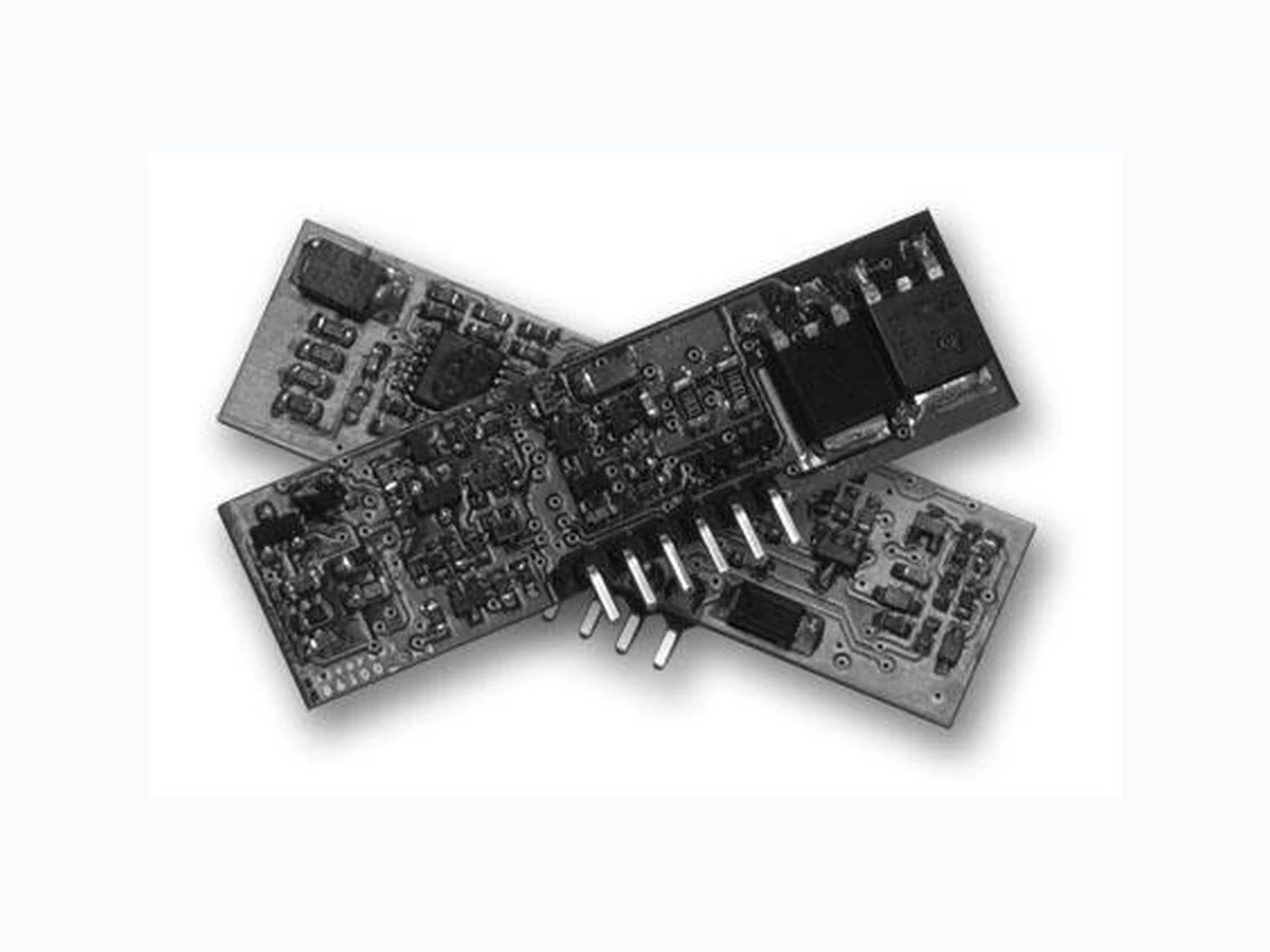
AG6100 SILVERTEL
Document overview
- Manufacturer or author: Provided By www.digicamel.com(FREE DATASHEET DOWNLOAD SITE)
- PDF pages: 13
Technical content
V1.8 Sept 2019 Datasheet Ag6100 POE+ Power-Sourcing-Equipment Module © Silver Telecom 2019 1 Silvertel 1. Features Compliant with IEEE802.3at Type 1(af) & Type 2 Small SIL package size - 53mm (L) x 14mm (H) Low cost Output power up to 39W Minimal (low cost) external components required Over-current and short circuit protection Industrial Temperature Range Silvertel “design-in” assistance 2. Description The Ag6100 is a single output Power Sourcing Equipment (PSE) module designed for use in IEEE802.3at Type 1 (af) and Type 2 Power over Ethernet (PoE) applications. The Ag6100 is capable of delivering up to 39W and is aimed at applications requiring PSE functionality such as CCTV DVR, home networking and industrial Ethernet. Ag6100 is a self-contained module, requiring just a few external components to provide a great deal of control and fe edback over each Powered Device (PD) that is connected to the PSE. PbPb
V1.8 Sept 2019 Data Sheet Ag6100 POE+ Power-Sourcing-Equipment Module © Silver Telecom 2019 4 4. Pin Description Pin # Name Description 1 VIN+ Main Power Supply. This pin connects to an isolated 45V to 57V supply; relative to the 0V. 2 0V 0V. This pin is the return path for the isolated VIN+ power supply. 3 STATUS Status Output. This output shows the status of the Ag6100. 4 Port+ Port Output. This output pin monitors the line and supplies power to valid powered device. 5 Port- Port Output Return. This pin is the return path for Port+. 6 NC No Connection. 5. Functional Description
5.1 Power Supplies
The Ag6100 only requires one power supply; to conform to the IEEE802.3at specification, this supply must be isolated from mains ground, as shown in Figure 3. Due to the power supply being capable of supplying up to 100W of power we would highly recommend protection in the form of a fuse to be fitted to positive input rail of the Ag6100. This will help prevent damage to the Ag6100 during an over voltage or over current event. 45V to 57V Ag6100 VIN+ ISOLATED FROM MAINS GROUND 1.5A Fuse Figure 3: Power Supply Connections
V1.8 Sept 2019 Data Sheet Ag6100 POE+ Power-Sourcing-Equipment Module © Silver Telecom 2019 5
5.2 Port Output
The Port output can be connected directly to the centre -tap of an IEEE802.3at compliant data transformer or to the spare pair connection for 10/100BASE-T applications, as shown in Figure 4 . For 1000BASE -T (Gigabit) Ethernet applications all four cable pairs require magnetics, this is explained in more detail in application note “ANX -1000BASE-T- CONNECTIONS”. Ag5100 VIN+ VIN- POWERED DEVICE (PD) POWER SOURCING EQUIPMENT (PSE) - + - + BR1 BR2 Ag6100 VIN+ Port- 45V to 57V ISOLATED Port+ Figure 4: Typical Connection Diagram
V1.8 Sept 2019 Data Sheet Ag6100 POE+ Power-Sourcing-Equipment Module © Silver Telecom 2019 7 The IEEE802.3at separ ates the power handling into two basic categories “Type 1” and “Type 2”. In simple terms Type 1 handles power requirements up to 15.4W and is comparable with the IEEE802.3af specification. Type 2 handles the power leve ls above this, which is commonly referred to as POE+.
6.1 Signature Detection
To ensure that the Ag6 100 does not apply power to a non PoE enabled device the Port output first checks for a valid PoE signature. The PD should present a nominal 25kΩ (23.75kΩ to 26.25kΩ) Signature resistance; if the Ag6100 does not see a valid signature then it will disconnect, wait approximately 2 seconds then try again, see Figure 7 below. Signature Open Circuit Voltage ~2sec Figure 7: Signature Cycle Time
6.2 Classification
On completion of a valid signature, the Ag6 100 will then interrogate t he PD to see if a classification signature is present. The classification signature is used to determine the amount of power the PD will draw and limits the output power a ccordingly (see Table 2). It is optional for the PD to present a classification signature and the Ag6 100 will default to Class 0 if the PD does not present one. If the Ag6100S sees a current over 48mA it will detect this as ‘Over Current’ and will retry the signature after a 2 second delay. Table 2 shows the measured current limits that the Ag6 100 uses to assign a classification value. Measured Current Classification 0mA to 6.5mA Class 0 >6.5mA to 14.5mA Class 1 >14.5mA to 23mA Class 2 >23mA to 33mA Class 3 >33mA to 48mA Class 4 Table 2: Classification Table
V1.8 Sept 2019 Data Sheet Ag6100 POE+ Power-Sourcing-Equipment Module © Silver Telecom 2019 8
6.3 Maintain Power Signature
On successful completion of a valid signature (and classification ) the Ag6100 will apply main power to the Port output and the STATUS output will go to Logic 1. Once main power has been applied , the Ag6100 with constantly monitor the PD to ensure that it is still connected; this is referred to as the Maintain Power Signature (MPS). The Ag6100 uses the dc detection method of MPS and will remove power if the current drawn falls below the detect threshold. If the Ag6100 Port output current is ≥10mA the output will remain on. If the Port output current is ≤5mA the output will be turned off and the Ag6100 will return to the signature cycle (looking for a valid signature).
6.4 Output Current Limits
The Ag6100 has two over current limits - Current Limit 1* and Current Limit 2*. The Ag6100 will allow the Port output to exceed Current Limit 1 (but not Current Limit 2) for a short duration – TLIM1*. If the Port output continues to exceed Current Limit 1; the output power will be removed and the STATUS o utput will indicate a n over-current fault (See Section 7 – STATUS Output). If the output exceed s Current Limit 2, the Ag6100 will remove power (without waiting for TLIM) and the STATUS output will indicate and over-current fault. *Note: See Section 9.3 Electrical Characteristics
6.5 Output Power
The Ag6100-S is capable of delivering up to 39W, when supplied with its maximum input voltage of 57V. Please note this is not the power available at the input of the Powered Device (PD) . There are cable, connector and polarity protection losses to be taking into account. 7. STATUS Output The STATUS output pin is at Logic 0 when the Port output is disconnected. After completion of a valid signature (and classification) the STATUS output will go to Logic 1 at the same time as the Port output applies main power. When the Port output is disconnected the STATUS output will go to Logic 0, see Figure 8.
V1.8 Sept 2019 Data Sheet Ag6100 POE+ Power-Sourcing-Equipment Module © Silver Telecom 2019 11 Isolated Power Supply Ag6100 VIN+ Port+ Port- SMAJ58A RJ45Data Transformer 10K STATUS 10K 10K LED1 R3BC846W Figure 12: STATUS Output Configuration 8. Protection
8.1 Input Protection
The Ag6 100 has built -in Tranzorb diode across its input, to protect the module from transients from the power supply. For further protection we would recommend a 1.5A slow blow fuse to be fitted in line with the positive input rail due to the high power capability of the power supply as described in section 5.1 and shown in Figure 3.
8.2 Output Short-Circuit Protection
In addition to the over -current protection the Ag6100 has built -in output short -circuit protection. If the Port output is shorted, the Ag6100 will limit the current and remove the power, the STATUS output will indicate a short-circuit fault. To protect the module from voltage transients coming from the RJ45 cable we would recommend fitting a SMAJ58 or higher on the Ag6100 output as shown in Figure 12.
V1.8 Sept 2019 Data Sheet Ag6100 POE+ Power-Sourcing-Equipment Module © Silver Telecom 2019 12 9. Electrical Characteristics
9.1 Absolute Maximum Ratings1
Parameter Symbol Min Max Units 1 DC Supply Voltage VDD -0.3 60 V
2 Storage Temperature TS -40 +100 OC
Note 1: Exceeding the above ratings may cause permanent damage to the product. Functional operation under these conditions is not implied. Maximum ratings assume free airflow.
9.2 Recommended Operating Conditions
Parameter Symbol Min Typ Max Units
1 Input Supply Voltage VDD (Type1)
VDD (Type2) 50 57 V V
2 Ag6100-S Operating Temperature - TOP -40 25 85 Ta / OC
9.3 Electrical Characteristics
Parameter Sym Min Typ Max Units Condition
1 VDD Idle Supply Current IDD 8 15 mA
2 Signature Detection Voltage VSIGL
2.7 4.5 10.1 V V
3 Minimum Valid Signature RSIGL 15 kΩ
4 Maximum Valid Signature RSIGH 32 kΩ
5 Classification Voltage VCLASS 14.5 20.5 V 6 Classification Mark Voltage VMARK 6.9 10 V
7 Classification Threshold
5.5 13.5 21.5 31.5 45.2 6.5 14.5 7.5 15.5 24.5 34.9 50.8 mA mA mA mA mA Class 0 - 1 Class 1 - 2 Class 2 - 3 Class 3 - 4 Class 4 - Over- current
8 Maintain Power Signature IMPS 5 10 mA
9 Maximum Output Power @
W Type 1 Type 2
10 Current Limit 1 ILIM1 375
11 Current Limit 2 ILIM2 475
12 Current Limit 1 Cut-Off Time TLIM1 50
13 STATUS Output VOH
VOL 3.3 0.3 V V 0.5mA Max
V1.8 Sept 2019 Data Sheet Ag6100 POE+ Power-Sourcing-Equipment Module © Silver Telecom 2019 13 10. Package 8.0 (max) 14.0 (Recommended PCB hole diameter = 1.1 ± 0.05) Dimensions (in mm) are nominal unless otherwise stated 2.54 ± 0.05 0.64 ± 0.05 3.0 Ag6100 53.0 21.10 ± 0.05 Information published in this datasheet is believed to be correct and accurate. Silver Telecom assumes no liability for errors which may occur or for liability otherwise arising out of use of this information or infringement of patents which may occur as a resul t of such use. No license is granted by this docu ment under patents owned by Silver Telecom or licensed from third parties by Silver Telecom. The products, their specification and information appearing in this document are subject to change by Silver Telecom without notice.