
DATASHEET SEARCH SITE
Document overview
- Manufacturer or author: Provided By www.digicamel.com(FREE DATASHEET DOWNLOAD SITE)
- PDF pages: 12
Technical content
V1.2 May 2014 Datasheet Ag301 Wireless Power Modules Silvertel © Silver Telecom 2014
1 Features
¾ Qi Compatible ¾ Output Power 5W ¾ Size 31.19mm x 22.88mm x 4.1mm ¾ Output Overload & Short-circuit Protection ¾ Simple Integration
2 Description
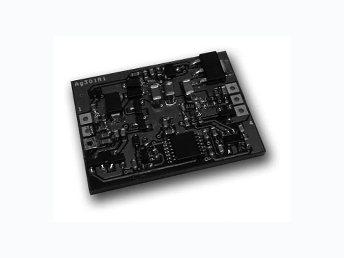
The Ag301 is a wireless charging receiver m odule; designed to work with the Ag311 or any other Qi compliant wireless power transm itter, typically used in wireless charging applications. With the increased use of m obile & portable devices, the Ag301 & Ag311 wireless power modules offer a wide range of benefits: - There are no cables to get tangled and you don’t have the problem of having different plugs or sockets for various devices. There is no risk of electrical shock, as there are no exposed metal parts. Can be used in explosive environments as there are no contacts to cause sparks. This means that there is no contact degradation due to friction, corrosion or abrasion. The units can be completely sealed for use in harsh environments, as its operation is not affected by dirt, dust, wa ter or chemicals and can even be used underwater. Can be used in medical environment where disinfecting and sterilization is required. PbPb
V1.2 May 2014 Datasheet Ag301 Wireless Power Modules
2.1 Table of Contents
2.2 Table of Figures
© Silver Telecom 2014
V1.2 May 2014 Datasheet Ag301 Wireless Power Modules
3 Ag301 Product Selector†
Part Number Input Voltage Output Voltage Maximum Output Current Type Ag301 5V 1000mA Receiver † The Ag301 fully meets the requirements of the RoHS directive 2002/95/EC on the restriction of haz ardous substances in electronic equipment. Table 1: Ordering Information Figure 1: Ag301 Block Diagram Purchasing Options: Large volume customers of typically 100K+ can purchase the STX15 controller IC on its own and Silvertel will supply the applications circuit so the customer can assemble it themselves. © Silver Telecom 2014
V1.2 May 2014 Datasheet Ag301 Wireless Power Modules
4 Pin Description
4.1 Ag301
1 CL1 Coil (Input). This pin connects to one side of the receive coil.
2 TCUT
Thermal Cut Off (Input). This pin has a pull up in the STX15 controller to an internal 3.3V reference rail. Pulling this input low will force an error message to be sent to the transmitter. 3 CL2 Coil (Input). This pin connects to the other side of the receive coil. 4 VDC- DC Return. This pin is the return path for the +VDC output.
5 Charged
Charged (Input). This pin has a pull up in the STX15 controller to an internal 3.3V reference rail. Pulling this input low will send a charged message to the transmitter. 6 VDC+ DC Output. This pin provides the regulated 5V output. Figure 2: Ag301 Package Format © Silver Telecom 2014
V1.2 May 2014 Datasheet Ag301 Wireless Power Modules
5 Functional Description
5.1 Wireless Power Overview
When the Ag311 wireless transmitter is connected to a 19V supply, it will start up and will commence looking for an Ag301 wireless receiver in range. It does this by applying a short power signal to the transmit coil to detect an object. If an object is detected then this signal is exten ded, looking for a Ping data message back from the receiver. If a valid Ping message is not received, the transmitter will remove the power signal and wait ~500ms before repeating the above process. If a valid “Ping” message is received, the pow er signal is maintai ned and the transmitter looks for the “Identification & Configuration” message and the “Power Transfer” message. If either the “Identification & Configuration” or the “Power Transfer” messages are invalid, the transmitter will remove the power signal and wait ~500ms before repeating the above steps. If the transmitter receives valid data, it wil l maintain and adjust the power signal in accordance with the data sent back from the receiver. Figure 3: Charger Overview © Silver Telecom 2014
V1.2 May 2014 Datasheet Ag301 Wireless Power Modules
5.2 Coils and Alignment
The wireless power connection is established through transmit and receive coils. For the Ag301 we recommend either an Elytone YT -28136, a Vishay IWAS-4832FF-50 or an equivalent. The nominal alignment position of the coils is shown below in Figure 4 and 5. In Figure 4 you can see that the coils are separated by the transmitter and receiver enclosures. The Qi specificat ion allows the transmitter enclo sure thickness to be between 1.5mm to 2.25mm, and the receiver enclosure thickness to be bet ween 0mm to 2.5mm. The Ag311 has been designed to meet this s pecification and the Ag301 is capable of operating well beyond the 2.5mm specification. Figure 4: Horizontal View Figure 5: Vertical View © Silver Telecom 2014
V1.2 May 2014 Datasheet Ag301 Wireless Power Modules
5.3 Control Inputs
The Ag301 has two optional control inputs: – Thermal Cut Off and Charged. Both of these inputs hav e pull-ups to an inter nal 3.3V reference. They can be driven directly from a controller (of l ogic gate) that has a 3. 3V rail, or via an external transistor if the external rail is not 3.3V (see Figure 8). It is important that if Figure 8 “Option A” is used, that the Controller outputs are tri-state or high at start-up. If this is an issue then “Option B” may be a better solution. The two transistors do not need to be anything special and could bot h be in a dual package, if required. The resistors can be high values (100K Ω) and could be in a quad package if required. TCUT Ag301Controller 3.3V Charged TCUT Ag301 Charged Controller Option A Option B Figure 8: Control Inputs
5.3.1 Thermal Cut Off
The Thermal Cut Off input (TCUT) can be used with an external circuit for battery protection. When this input is pulled low, the Ag301 will send an error message back to the Transmitter. If the Ag311 is bein g used, it will power cycle twic e to see if the error can be cleared, but if the error is still present after this, it will remain off and show an error code.
5.3.2 Charged
The Charged input can be used to send a message back to the transmitter when the battery is fully charged. When this input is pulled low, the Ag301 w ill send a message back to the Transmitter saying that the charge is complete. © Silver Telecom 2014
V1.2 May 2014 Datasheet Ag301 Wireless Power Modules
6 Typical Connections
The Ag301 is very easy to implement, Figure 9 shows typical application drawing, giving a basic overview. Ag301 Receiver Enclosure Load CL1 CL2 Charge Controller Bat VDC+ VDC- TCUT Charged Therm Rx Coil +5V Q1a Q1b R1a R1b R1c R1d Figure 9: Typical Application Drawing
7 Typical Applications
The Ag301 can be used in a wide range of wir eless power and charging applications and with the increased use of mobile & portable devices this list is expanding every day. At present one of the biggest market sectors for wireless charging are in mobile phones. But there are many more applications that can benefit from the adv antages of wireless power transfer. Because there are no contacts to cause sparks, wireless charging can be used in environments where combustible materials or gases are present. Also as the transmitter and receiver can be built into completely sealed enclosures; they can be used in harsh environments, where dust, dirt, water or chemicals are present. On the other end of the spectrum, wireless power also lends itself for use in clean environments, where disinfecting and sterilization is required. © Silver Telecom 2014
V1.2 May 2014 Datasheet Ag301 Wireless Power Modules
8 Operating Temperature
The Ag301 has to rectify and regulate the volt age received from the (Ag311) transmitter. The losses incurred by these processes will re sult in the module g enerating heat and as a result this will need to be taken into consideration. The amount of heat gener ated by the module is primarily related to the current being drawn by the load. So care needs to be tak en to control the ambient temperature around the module. The Ag301 has a maximum ambient operating temperature of 70 °C, as shown in Figure 10. These results were preformed in an environmental chamber (Associated Environmental Systems – SD-302), without any heat-sinking. Output Power (mA) Figure 10: Ag301 Operating Temperature Profile
9 Output Protection
9.1 Over Current Protection
The Ag301 output has an over current protection threshold set to ~1.2A. If the load attempt to draw > ~1.2A it will disconnect the output and report an over current error back to the transmitter.
9.2 Short Circuit Protection
The Ag301 output is capable of handling a direct short circuit without any damage to the module. Note: recovery from the above output protection conditions will depend on the transmitter being used. © Silver Telecom 2014
V1.2 May 2014 Datasheet Ag301 Wireless Power Modules
10.1 Absolute Maximum Ratings*
Parameter Symbol Min Max Units
1 Storage Temperature TS -40 +100 °C
2 Control Inputs Maximum DC Rating VIN -0.3 3.5 V *Exceeding the above ratings may cause permanent damage to the product. Functional operation under these conditions is not implied. Maximum ratings assume free airflow.
10.2 Recommended Operating Conditions
Parameter Symbol Min Typ Max Units
1 Operating Temperature TOP -20 25 70† Ta / °C
2 Maximum Input Voltage (From Coil) VINC 10 Vp-p
†See Section 8
10.3 DC Electrical Characteristics*
DC Characteristic Sym Min Typ* Max Units Test Comments 1 Output Voltage VOUT 4.75 5 5.25 V @ 50% Load
2 Output Current IOUT 1 A
3 Over-Load Current IOL 1.2 A
4 Load Regulation VREG 2 %
5 Peak Efficiency EFF 71.29 % With Ag311
6 Short Circuit Duration TSC ∞ sec
7 Minimum Load IMIN 0 mA
8 Output Ripple and Noise
(Minimum Load)1 VRN1 100 mVp-p
9 Output Ripple and Noise
(Maximum Load)
1 VRN2 157 mVp-p
10 Maximum Start Up
ST 7 mm @ Full Load
11 Maximum Operating
OP 12 mm @ Full Load
12 Control Inputs Logic Low
IL 0.75 V
13 Control Inputs Logic
IH 2.25 V *Typical figures are at 25°C and are for design aid only. Not Guaranteed 1: This can be reduced with additional output capacitance or filter. © Silver Telecom 2014
V1.2 May 2014 Datasheet © Silver Telecom 2014 Ag301 Wireless Power Modules 31.19 1.623 8.89 2.54 22.86 27.94 1.6 Max 2.5 Dimensions (in mm) are nominal unless otherwise stated 2.54 Information published in this datasheet is believed to be correc t and accurate. Silver Telecom assumes no liability for errors which may occur or for liability otherwise arising out of use of this information or infringement of patents which may occur as a result of such use. No license is granted by this document under patents owned by Silv er Telecom or licensed from thir d parties by Silver Telecom. The products, their specification and information appearing in this document are subject to change by Silver Telecom without notice.