
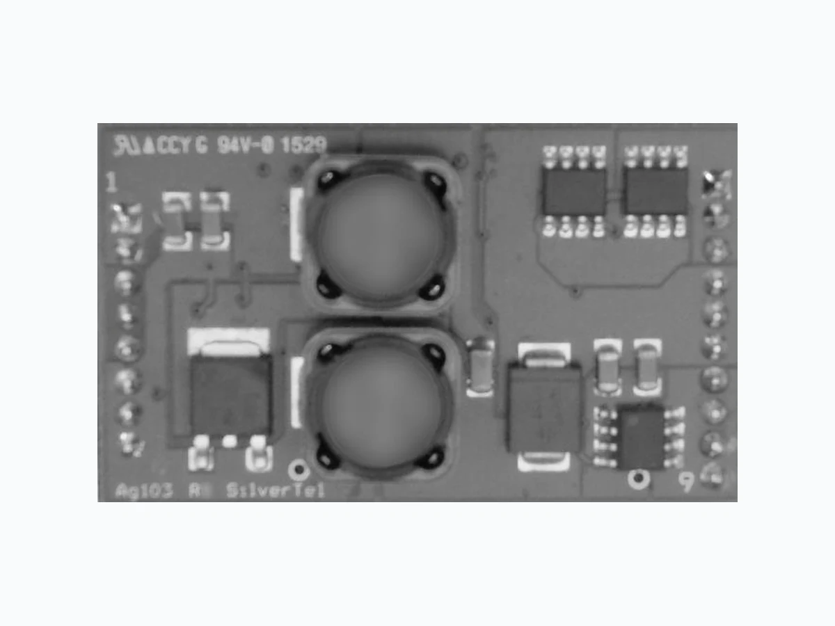
AG103 SILVERTEL
Document overview
- Manufacturer or author: Provided By www.digicamel.com(FREE DATASHEET DOWNLOAD SITE)
- PDF pages: 19
Technical content
V1.2 September 2019 Datasheet Ag103 Intelligent Sealed Lead Acid Solar Battery Charger Module © Silver Telecom 2019 Silvertel
1 Features
Multi-Stage Charging Solar Panel or DC Input Maximum Power Point Tracking (MPPT) Very Low Power Consumption Wide DC Input Voltage Range High Efficiency DC-DC Converter Intelligent ‘Top-up’ Float Charge Programmable Charge Current Battery Condition Indicator Temperature Compensation Overload & Short-circuit Protection Simple Integration
2 Description
The Ag103 is a micro-processor based intelligent, low cost, sealed lead acid (SLA) battery charging module designed to be used with solar panels . It uses digital technol ogy to optimise the charging of 12V sealed lead acid batteries between 1.2Ah and 12Ah capacity. Using intelligent charging techniques, including maximum power point tracking, the Ag103 technology maximises both battery lifetime and the amount of power derived from the solar panel. The Ag103 can take a dc input range of 9V to 36V DC, t his gives great flexibility allowing the system and charger to use a variety of power levels of solar panels, or a low cost power supply. PbPb
V1.2 Sept 2019 Data Sheet © Silver Telecom 2019 Ag103 Sealed Lead Acid Solar Battery Charger Module Table of Contents
2.1 Table of Figures
V1.2 Sept 2019 Data Sheet © Silver Telecom 2019 Ag103 Sealed Lead Acid Solar Battery Charger Module Ag103 Product Selector Part Number Input Voltage Output Voltage Battery Capacity Marking Package Ag103* 9V to 36V 12V 1.2Ah to 12Ah Ag103 DIL * The Ag103 complies with the European Directive 2011/65/EU for the Restriction of use of certain Hazardous Substances (RoHS) including Directive 2015/863 published in 2015, amending Annex II of Directive 2011/65/EU. Moisture Sensitive Level 1 and HBM 1. Table 1: Ordering Information Vin+ GND CS THERM Bat- Bat+Input PWR Input GND 470uF STAT Ag103 μ-Controller DC:DC Converter Current Sense Thermal Management Battery Monitor Capacity Select Internal Reference Voltage Load switch through Load Load EnableLE Figure 1: Block Diagram with External Components
V1.2 Sept 2019 Data Sheet © Silver Telecom 2019 Ag103 Sealed Lead Acid Solar Battery Charger Module
3 Pin Description
1 VIN+ Positive Supply (Input). This pin connects to a positive dc supply (9V to 36V). 2 VIN+ Positive Supply (Input). This pin connects to a positive dc supply (9V to 36V). 3 CS Capacity Select (Input). This pin connects to an external resistor to set the capacity of the battery to be charged (1.2Ah to 12Ah). 4 STAT Charge Status (Output). This output pin is used to indicate the system status. 5 LE Load Enable (Input). Connect this pin to GND via a 2k resistor to permanently connect the battery to the load. Leave open circuit for battery back up mode. 6 GND Ground Return (Input). This pin connects to the ground return of the power supply. 7 GND Ground Return (Input). This pin connects to the ground return of the power supply. 8 GND Ground Return (Input). This pin connects to the ground return of the power supply.
9 BAT-
Battery Negative (Output). The output pin connects to the battery negative terminal. It must NOT be connected directly to the GND pin.
10 BAT-
Battery Negative (Output). The output pin connects to the battery negative terminal. It must NOT be connected directly to the GND pin.
11 BAT-
Battery Negative (Output). The output pin connects to the battery negative terminal. It must NOT be connected directly to the GND pin. 12 THERM Thermistor (Input). The pin can be connected to an external thermistor to add temperature compensation (if required). 13 BAT+ Battery Positive (Output). The output pin connects to the battery positive terminal. 14 BAT+ Battery Positive (Output). The output pin connects to the battery positive terminal. 15 BAT+ Battery Positive (Output). The output pin connects to the battery positive terminal.
16 Load
Load Output (Output). The Load output pin connects the battery positive terminal to the users load.
17 Load
Load Output (Output). The Load output pin connects the battery positive terminal to the users load.
18 Load
Load Output (Output). The Load output pin connects the battery positive terminal to the users load.
V1.2 Sept 2019 Data Sheet © Silver Telecom 2019 Ag103 Sealed Lead Acid Solar Battery Charger Module Top View Ag103 J1 J2 Figure 2: Ag103 DIL Package Format
V1.2 Sept 2019 Data Sheet © Silver Telecom 2019 Ag103 Sealed Lead Acid Solar Battery Charger Module
4 Functional Description
4.1 Operation
In many safety critical systems it is essential that the battery is charged quic kly with no stress or damage . Battery manufacturers also recommend using multi -stage charging to reduce the stress on the battery while giving the s hortest possible charge time. The Ag103 achieves this using an optimum multi-stage charge cycle, shown in Figure 3. Charge Current Charge Voltage Battery Voltage / Charge Current Charging Time Constant Current (Bulk Charge) Float Charge Two Stage Constant Voltage (Absorption/Float Charge) Figure 3: Basic Ag103 Charge Profile The Ag103 implements the ideal charging cycle by applying a higher bulk charge voltage for 70% - 80% of the charge cycle and a lower absorption charge voltage for the remaining 20% - 30%. This is done to prevent the battery from gassing as it approaches full charge. Once the battery has reached the optimum level, the Ag103 will maintain an accurate float voltage to keep the battery topped up. The charge profile can be further optimised by using thermal compensation (see Section 4.5).
V1.2 Sept 2019 Data Sheet © Silver Telecom 2019 Ag103 Sealed Lead Acid Solar Battery Charger Module
4.2 Input
The Ag103 can take either a solar panel input or a very wide dc input range of 9Vdc to 36Vdc, making this module extremely flexible. For stable operation it is recommended to fit a 470μF capacitor across the input pins, this should be placed as close to these pins as possible. The Ag103 can also be powered from an AC power supply with the addition of an external bridge rectifier. It is important that the rectified voltage across the input pins is within the 9Vdc to 36Vdc limits, Figure 4 shows examples of these inputs. Ag103 GND VIN+ DC Input 470uF +Vdc -Vdc Ag103 GND VIN+ AC Input 470uF Vac Vac Ag103 GND VIN+ 470uF +Vdc -Vdc Solar Input Figure 4: Input Connections – Solar, DC or AC Input
V1.2 Sept 2019 Data Sheet © Silver Telecom 2019 Ag103 Sealed Lead Acid Solar Battery Charger Module For a solar panel input Table 2 below shows various 12V* panel sizes that can be chosen to charge different size batteries. Panel Power (W) Panel Current (A) Matched battery Size (optimum) Maximum battery size panel can charge 5W 0.29 1.2Ah 2.8Ah 10W 0.58 2.3Ah or less 5.8Ah 20W 1.14 4Ah or less 11Ah 30W 1.74 7Ah or less 17Ah 40W 2.33 9Ah or less 23Ah 50W 2.85 12Ah or less 28Ah Table 2: Panel Selection * Majority of panels are referred to as 12V panels but their open circuit voltage is 21V.
4.3 Capacity Select
The Ag103 is capable of being programmed to charge a range of SLA batteries from 1.2Ah up to 12Ah, by connecting a resistor between the CS pin and the GND pin, see Figure 5. Ag103 GND CS Capacity Select RCS Figure 5: Capacity Select The CS pin has an internal pull up resistor to a voltage reference which sets the voltage on this pin. This voltage is measured at start-up and the optimum charge profile for the battery is programmed. The value of RCS is shown in Table 3.
V1.2 Sept 2019 Data Sheet © Silver Telecom 2019 Ag103 Sealed Lead Acid Solar Battery Charger Module Battery Capacity (Ah) RCS Resistance (Ohms)* Min Input Voltage (V) Voltage at the CS Pin (V) Bulk Charge Current Limit (A) ±10% 1.2 1K ±1% 9 0.3 0.3 2 2K ±1% 9 .55 0.5 2.1 3K ±1% 9 .76 0.525 2.3 3K9 ±1% 9 .93 0.575 2.8 4K7 ±1% 9 1.05 0.7 3.2 6K2 ±1% 12 1.26 0.8 4 6K8 ±1% 12 1.30 1 7 7K5 ±1% 12 1.37 1.2 12 9K1 ±1% 12 1.52 1.2 Table 3: Value of RCS * To prevent damaging the battery it is important that the correct value of RCS is set. If RCS is not fitted, then the Ag103 will default to 1.2Ah capacity.
4.4 Load Enable
The Ag103 can either connect the battery constantly to the load by connecting a 2k resistor between LE and GND, see Figure 9, or it can be used in a battery back up mode where the battery is only connected to the load if the internal μ-controller detects the input has been disconnected, or the panel voltage has dropped below 9V. This mode is selected by leaving the LE open circuit, see figure 10.
4.5 Thermal Compensation
The optimum terminal voltage for the charging pro cess is also depend ent on battery temperature. This is because the electrochemical activity is affected by temperature changes. Therefore, as the temperature rises, the charging voltage should be reduced to prevent overcharge . Likewise as the temperature falls, the charge voltage should be increased to avoid undercharge. In order to maximise the life of the battery the use of temperature compensation is recommended. The Ag103 makes this easy to implement with only the addition of a low cost Thermistor . The Ag103 measures the THERM pin and will automatically adjust the charge profile to compensate for any changes in battery temperature. A typical recommended value for TH1 as shown in Figure 6 is a 47K NTC (Negative Temperature Coefficient) resistor with B25/50 ~4000K. These are inexpensive and readily available in surface mount or bead format. For correct operation the Thermistor must be in physical contact with the battery.
V1.2 Sept 2019 Data Sheet © Silver Telecom 2019 Ag103 Sealed Lead Acid Solar Battery Charger Module TH1 THERM Bat- Bat+ (Input) GND Ag103 Figure 6: Output Adjustment When using thermal compensation, if the battery temperature exceeds 50 ˚C, the Ag103 will shut-down the DC -DC converter and the output status indicator (STAT) will report an over temperature error. The Ag103 will default to a 25˚C charge profile if TH1 is not fitted.
V1.2 Sept 2019 Data Sheet © Silver Telecom 2019 Ag103 Sealed Lead Acid Solar Battery Charger Module
4.6 Status Output
The Ag103 has a status indication output pin ‘STAT’; that can be connected to a μ- controller input for full status monitoring or can be used with an LED as an indicator (as shown in Figure 7). Ag103 (Input) GND To μ-controller STAT (+3V3) Internal Reference Voltage μ-controller BC846W LED Ag103 STAT 330R 10K VIN+ (+3V3) Internal Reference Voltage μ-controller 10K Figure 7: STAT Output Configurations Table 4, shows the different mode conditions of the Ag103: - Mode Status Mode STAT Output
0 Bulk Charge Operation Steady State ‘Logic 1’
1 Float Charge 50% ‘Logic 1’ 50% ‘Logic 0’
2 Over Current Error 1 Pulse
3 Over Temperature Error 2 Pulses
4 Disconnected Battery Error 3 Pulses
5 Input Voltage Removed / No Solar Power Steady State ‘Logic 0’
Table 4: STAT Output Conditions
4.6.1 Mode 0 – Bulk Charge Operation
Once the Ag103 has checked the battery capacity and sees a 12V battery connected it will power up and the ‘STAT’ pin will output a steady state 'logic 1'. The Ag103 will continue to output this state until the battery has reached it's 80 % charge before switching to float charge and entering Mode 1.
V1.2 Sept 2019 Data Sheet © Silver Telecom 2019 Ag103 Sealed Lead Acid Solar Battery Charger Module
4.6.2 Mode 1– Float Charge
After the battery has reached it's 80% charge the Ag103 will change it's charging status to float charge by dropping it's terminal voltage down to ~13.65V. The 'STAT' pin will drop to a logic 0 for 1s and then back to a logic 1 for 1s. This cycle will repeat itself over the period of its float charge.
4.6.3 Mode 2 – Over Current
If an output over current condition is detected, the Ag103 will shutdown its DC -DC converter and will go into Mode 2. The STAT pin will drop to a logic 0 for 100ms, followed by a logic 1 for 100ms before returning to a logic 0. The Ag103 will then reset and wait 2 seconds before re -attempting to power up . If the over current is still there when trying to power up, the Ag103 will immediately shut back down and repeat the process. Once the over current has been removed the Ag103 will return to Mode 0 (bulk charge operation).
4.6.4 Mode 3 – Over Temperature
If a battery over temperature condition occurs, the Ag103 will shutdown its DC -DC converter to protect the battery and enter Mode 3. The STAT pin will drop to a logic 0 for 100ms before generating two logic 1 pulses , with a 100ms mark and 100ms space. This will repeat over a 2s period until the batte ry temp erature has dropped below 50 ˚C (the maximum operating temperature). Once the battery temperature has dropped below 50˚C the Ag103 will return to Mode 0 (bulk charge operation).
4.6.5 Mode 4 – Disconnected battery
If the battery is disconnected or there is no b attery present at power up, the Ag103 will shutdown its DC -DC converter , go into Mode 4 and output three 100ms logic 1 pulses, with a 100ms mark and 100ms space . This will repeat over a 2s period until a 12V battery is connected. When a 12v battery is connected the Ag103 will go into Mode 0 (bulk charge operation).
4.6.6 Mode 5 - Input Voltage Removed/ No Solar Power
When the input voltage is removed or the solar panel can no longer provide any power to the Ag103, the STAT pin will output a logic 0 until power has been reconnected or the panel can provide enough power to charge the connected battery. Figure 8 shows the timing of the STAT output in more detail: -
V1.2 Sept 2019 Data Sheet © Silver Telecom 2019 Ag103 Sealed Lead Acid Solar Battery Charger Module Mode 3 Logic 0 Logic 1 Logic 0 Logic 1 Logic 0 Logic 1 Mode 2 Mode 1 100ms Start of error events Mode 4 Logic 0 Logic 1 Mode 5 Logic 0 Logic 1 Mode 0 2s Power up Logic 0 Logic 1 1s 1s Error Events Working Operation 100ms 2s 2s 2s 2s 2s 2s 2s 2s 100ms Attempt Re-power Input power removed Figure 8: STAT Output Timing
V1.2 Sept 2019 Data Sheet © Silver Telecom 2019 Ag103 Sealed Lead Acid Solar Battery Charger Module
5 Typical Application
The Ag103 is ideal for solar powered applications such as roadside warnings, parking meters and LED street lighting. Figure 9 shows a very simple method of connecting the Ag103 for this application where the power is permanently connected to the load. However if your application requires only to be used as a battery back up system, for example emergency lighting, alarm systems, door access control and UPS, then a typical application is shown in figure 10. C1 should be positioned as close to the input pins as possible and TH1 should be in physical contact with the battery. It is also very important that the GND and Bat - pins are not connected together as this could permanently damage the battery. Input PWR Input GND Bat + * Note: TH1 = 47K NTC, B(K) = 4000 Load Over-current /Battery reversal protection: D1 = SK154 or Equivalent Fuse = 10A Slow Blow Ag103 GND VIN+ 470uF +Vdc -Vdc Solar Input TH1 Bat - THERM Load Output FUSE LE Permanent Load Figure 9: Typical Application - Permanent Load
V1.2 Sept 2019 Data Sheet © Silver Telecom 2019 Ag103 Sealed Lead Acid Solar Battery Charger Module Input PWR Input GND Bat + * Note: TH1 = 47K NTC, B(K) = 4000 Load Over-current /Battery reversal protection: D1,D2 = SK154 or Equivalent Fuse = 10A Slow Blow Ag103 GND VIN+ 470uF +Vdc -Vdc TH1 Bat - THERM Load Output FUSE Battery Back Up Figure 10: Typical Application - Battery Back Up
V1.2 Sept 2019 Data Sheet © Silver Telecom 2019 Ag103 Sealed Lead Acid Solar Battery Charger Module
6 Operating Temperature Range
For most applications the Ag103 will be positioned close to the battery and the maximum operating temperature will be limited by the battery to 50˚C. However if the battery is being charged remotely, then the Ag103 can be operated from -20˚C to +70˚C.
7 Protection
The Ag103 offers four primary protection circuits: -
7.1 Over Current & Short Circuit Protection
The Ag103 output has over current and short circuit protection. This is triggered when the output current exceeds 200mA above the bulk charge current shown in Table 3. If an over current fault is detected, the Ag103 will shut -down the DC -DC converter and the STAT output will report an over current error.
7.2 Over Temperature Protection
This can only be activated if the thermal compensation thermistor is fitted . If the battery temperature exceeds 50˚C, the Ag103 will shut -down the DC-DC converter and the STAT output will report an over temperature error.
7.3 Low Battery Terminal Voltage Protection
If the battery terminal voltage is <7V, the Ag103 Status output will report Mode 4 and the Ag103 will remain idle and wait until a 12V battery has been connected. This is primarily to protect the user from accidentally connecting a 6V battery to the Ag103. It also protects the Ag103 from being connected to a damaged or a deep discharged battery.
7.4 Deep Discharge Protection
The Ag103 constantly monitors the terminal voltage of the battery. If the load connected draws too much power or has been constantly drawing power from the battery causing the terminal voltage to fall below 10.5V, the Ag103 will disconnect the load from the battery to stop it being deep discharged. The Ag103 will only allow the load to be reconnected once the terminal voltage on the battery recovers to 12.5V or higher.
7.5 Battery Reversal
The Ag103 does not provide battery reversal protection, however Figure 9 shows a simple method of providing this safety feature. This also provides protection for an over-current or short on the Load Output pin.
V1.2 Sept 2019 Data Sheet © Silver Telecom 2019 Ag103 Sealed Lead Acid Solar Battery Charger Module
8 Features
8.1 MPPT- Maximum Power Point Tracking
The Ag103 has MPPT built in which keeps the solar panel in a state where it can produce the maximum amount of power it is capable of. This optimises the amount of power harvesting from a solar panel, such that the maximum power is being delivered to charge the battery. The Ag103 constantly monitors the terminal voltage of a 12V solar panel and the amount of current it is drawing. If there is a cloudy day or limited amount of sun the solar panels voltage automatically folds over and the power output drops. The Ag103 tracks this drop and alters its charging profile/power to ensure it gets the maximum power out of the solar panel, thereby providing the maximum charge to the battery that can be achieved. Figure 11 below shows an example of the Maximum Power Point of a 20W panel. Figure 11: MPPT of a 20W solar panel
V1.2 Sept 2019 Data Sheet © Silver Telecom 2019 Ag103 Sealed Lead Acid Solar Battery Charger Module
9 Electrical Characteristics
9.1 Absolute Maximum Ratings*
Parameter Symbol Min Max Units 1 DC Supply Voltage VCC -0.3 40 V
2 Storage Temperature TS -40 +100 °C
*Exceeding the above ratings may cause permanent damage to the product. Functional operation under these conditions is not implied. Maximum ratings assume free airflow.
9.2 Recommended Operating Conditions
Parameter Symbol Min Typ Max Units
1 DC Input Supply Voltage VIN 9 12 36 V
2 Solar Input Voltage (open circuit) VIN 21 VOC
3 Operating Temperature TOP -20 25 70† Ta / °C
†See Section Operating Temperature Range
9.3 DC Electrical Characteristics*
DC Characteristic Sym Min Typ* Max Units Test Comments
1 Bulk Charge Constant
2 Input Current - Idle IIN 17 mA Disconnected
3 Battery Standby Current IBAT 10 mA No Input
4 Absorption Charge
Voltage 1 VOUT1‡ 14.2 14.4 14.6 V 5 Float Charge Voltage VOUT2‡ 13.5 13.65 13.8 V STAT Output Low Voltage Output High Voltage VOL VOH 3.3 0.5 V V
7 Output Ripple and Noise
(at the battery terminal) VRN 50 mVp-p 12Ah battery
8 DC-DC Converter
Efficiency EFFDC 87 % At 12V-18V input
9 Charger Efficiency EFFBAT 82 %
10 Short-Circuit Duration TSC ∞ sec
11 Load Output ILOUT 7 A 10A Fuse**
*Typical figures are at 25°C with a nominal input voltage = 12V and are for design aid only. Not Guaranteed ** Fuse to be fitted for protection against over current on the Load output pin. (see figures 9) ‡Measured between the GND and the BAT+ pins
V1.2 Sept 2019 Data Sheet © Silver Telecom 2019 Ag103 Sealed Lead Acid Solar Battery Charger Module 0.64 45.72 7.38 (Recommended PCB hole diameter = 1.1 ± 0.05) Dimensions (in mm) are nominal ± 0.25 unless otherwise stated 2.4 50.60 2.54 TYP 2.543.00 1.60 Top View Ag103 J1 J2 6.60 MAX Information published in this datasheet is believed to be correct and accurate. Silver Telecom assumes no liability for error s which may occur or for liab ility otherwise arising out of use of this information or infringement of patents which may occur as a result of such use. No license is granted by this document under patents owned by Silver Telecom or licensed from third parties by Silver Telecom . The products, their specification and information appearing in this document are subject to change by Silver Telecom without notice.