
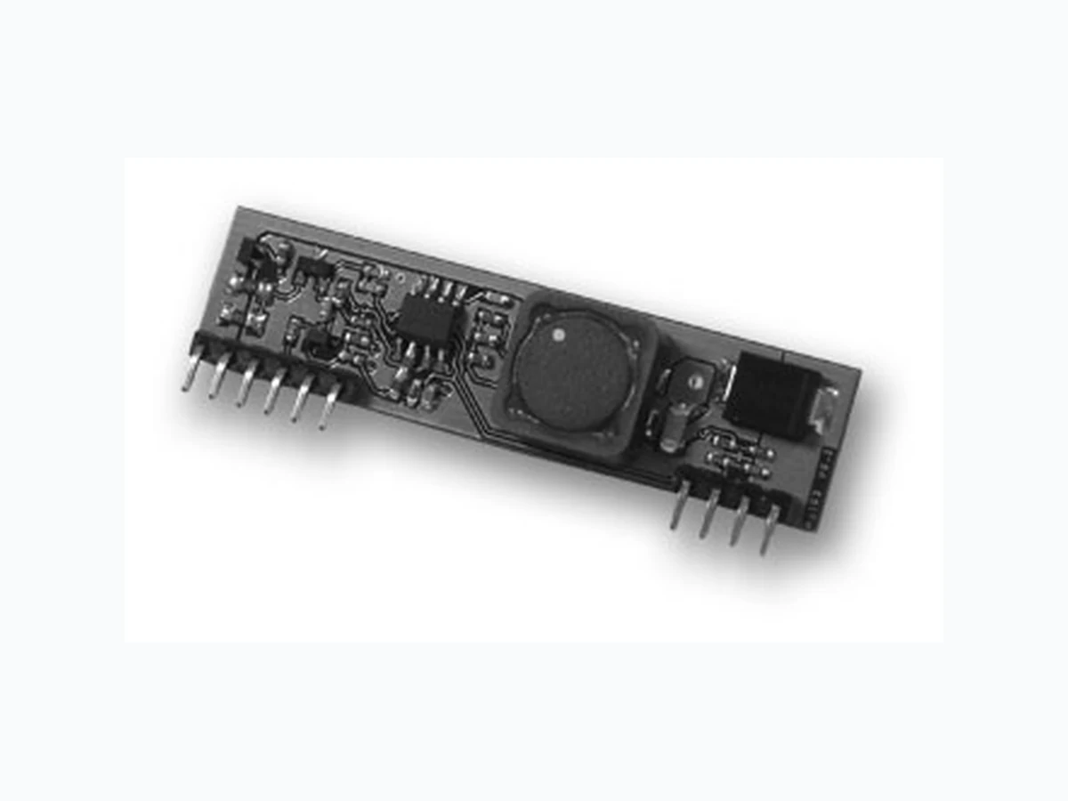
AG102 SILVERTEL
Document overview
- Manufacturer or author: Provided By www.digicamel.com(FREE DATASHEET DOWNLOAD SITE)
- PDF pages: 15
Technical content
V1.6 June 2014 Datasheet Ag102 Intelligent Sealed Lead Acid Battery Charger Module © Silver Telecom 2014 Silvertel
1 Features
¾ Multi-Stage Charging ¾ Battery Reversal Protection ¾ Reduced Power Consumption ¾ Wide DC or AC Input Voltage Range ¾ High Efficiency DC-DC Converter ¾ Intelligent ‘Top-up’ Float Charge ¾ Programmable Charge Current ¾ Battery Condition Indicator Output ¾ Temperature Compensation ¾ Overload & Short-circuit Protection ¾ Simple Integration
2 Description
The Ag102 is a micro-processo r based intelligent, cost effective, sealed lead acid (SLA) battery charging module. It uses digital technology to optimise the charging of standard, 12V sealed lead acid batteries between 1.2Ah and 7Ah capacity. Using various intelligent charging techniques the Ag102 technology will maximise the manufacturers specified battery lifetime. The Ag102 has a very wide input range of 9V to 36V DC. This gives extensive flexibility and means the system and charger requires just one, lower cost, power supply. When used in conjunction with Silvertel’s Power over Ethernet (PoE) m odule, the Ag102 can charge SLA batteries from power obtained over an Ethernet cable. PbPb
V1.6 June 2014 Data Sheet Ag102 Sealed Lead Acid Battery Charger Module Table of Contents
2.1 Table of Figures
© Silver Telecom 2014
V1.6 June 2014 Data Sheet Ag102 Sealed Lead Acid Battery Charger Module
3 Ag102 Product Selector†
Part Number Input Voltage Output Voltage Battery Capacity Marking Package Ag102S 9V to 36V 12V 1.2Ah to 7Ah Ag102 SIL † The Ag102 fully meets the requirements of the RoHS directive 2002/95/EC on the restriction of hazardous substances in electronic equipment. Table 1: Ordering Information Vin+ GND CS THERM Bat- Bat+Input PWR Input GND *Note: Default to 1.2Ah 470uF STAT Ag102 μ-Controller DC:DC Converter Current Sense & Polarity Protection Thermal Management Battery Monitor Capacity Select Internal Reference Voltage Figure 1: Block Diagram with External Components © Silver Telecom 2014
V1.6 June 2014 Data Sheet Ag102 Sealed Lead Acid Battery Charger Module
4 Pin Description
1 VIN+ Positive Supply (Input). This pin connects to a positive dc supply (9V to 36V). 2 VIN+ Positive Supply (Input). This pin connects to a positive dc supply (9V to 36V). 3 CS Capacity Select (Input). This pin connects to an external resistor to set the capacity of the battery to be charged (1.2Ah to 7Ah). 4 STAT Charge Status (Output). This output pin is used to indicate the battery status. 5 GND Ground Return (Input). This pin connects to the ground return of the power supply. 6 GND Ground Return (Input). This pin connects to the ground return of the power supply. 7 THERM Thermistor (Input). The pin can be connected to an external Thermistor to add temperature compensation (if required).
8 BAT-
Battery Negative (Output). The output pin connects to the battery negative terminal. It must NOT be connected directly to the GND pin.
9 BAT-
Battery Negative (Output). The output pin connects to the battery negative terminal. It must NOT be connected directly to the GND pin. 10 BAT+ Battery Positive (Output). The output pin connects to the battery positive terminal. Figure 2: Ag102 SIL Package Format © Silver Telecom 2014
V1.6 June 2014 Data Sheet Ag102 Sealed Lead Acid Battery Charger Module
5 Functional Description
5.1 Operation
When power is applied, the A g102 reads the CS input and sets the charge profile for the selected battery capacity (see Section 5.3). In many safety critical systems it is essent ial that the battery is charged quickly with no stress or damage. The Ag102 achieves this us ing an optimum multi- stage charge cycle, shown in Figure 3. Battery Voltage / Charge Current Figure 3: Basic Ag102 Charge Profile Battery manufacturers recommend using mult i-stage charging to reduce the stress on the battery while giving the shortest possible charge time. The Ag102 implements the ideal charging cycle by applying a higher bulk charge voltage for 70% - 80% of the charge cycle and a lower absorption charge voltage for the remaining 20% - 30%. This is done to prevent the battery from gassing as it approaches full charge. Once the battery has reached the optimum le vel, the Ag102 will continue to top up the battery using an intermittent float charge. The charge profile can be further optimised by using thermal compensation (see Section 5.4). © Silver Telecom 2014
V1.6 June 2014 Data Sheet Ag102 Sealed Lead Acid Battery Charger Module
5.2 Input
The Ag102 has a very wide input range of 9V dc to 36Vdc, making this module extremely flexible. For stable operation it is recommended to fit a 470 μF capacitor across the input pins, as close to these pins as possible. The Ag102 can be powered from an AC power supply with the addition of an external bridge rectifier. It is important that the rectified voltage across the input pins is within the 9Vdc to 36Vdc limits, Figure 4 shows examples of both methods. For optimum efficiency the input voltage should be set between 12V and 18V. Figure 4: Input Connections – DC or AC Input © Silver Telecom 2014
V1.6 June 2014 Data Sheet Ag102 Sealed Lead Acid Battery Charger Module
5.3 Capacity Select
The Ag102 is capable of charging a range of SL A batteries from 1.2Ah up to 7Ah. Setting the CS input couldn’t be easier, all that is required is a resistor between the CS pin and the GND pin, see Figure 5. Ag102 GND CS Capacity Select RCS Figure 5: Capacity Select The CS pin has an internal pull up resistor to a voltage reference which sets the voltage on this pin. This voltage is measured at start-up and the optimum charge profile for the battery is programmed. The value of R CS is shown in Table 2. Battery Capacity (Ah) R CS Resistance (Ohms)* Min Input Voltage (V) Voltage at the CS Pin (V) Bulk Charge Current Limit (A) ±10% 1.2 1K ±1% 9 0.5 0.3 2 2K7 ±1% 9 1 0.5 2.1 4K3 ±1% 9 1.5 0.525 2.3 6K8 ±1% 9 2 0.575 2.8 10K ±1% 9 2.5 0.7 3.2 15K ±1% 12 3 0.8 4 24K ±1% 12 3.5 1 7 43K ±1% 12 4 1 Table 2: Value of RCS * To prevent damaging the battery it is important that the correct value of RCS is set. If RCS is not fitted, then the Ag102 will default to 1.2Ah capacity. © Silver Telecom 2014
V1.6 June 2014 Data Sheet Ag102 Sealed Lead Acid Battery Charger Module
5.4 Thermal Compensation
The optimum terminal voltage for the chargi ng process is also dependent on battery temperature. This is because the electrochem ical activity is affected by temperature changes. Therefore, as the temp erature rises, the charging voltage should be reduced to prevent overcharge. Likewise as the tem perature falls, the char ge voltage should be increased to avoid undercharge. In order to a ttain optimum service life (maximising the life of the battery), the use of temperature compensation is highly recommended. The Ag102 make this easy to implement, with only the addition of a low cost Thermistor, connected so the battery temperature can be monitored. The Ag102 measures the THERM pin and will automatically adjust the charge profile to compensate for any changes in battery temperature. TH1* shown in Figure 6 is a 47K NTC (Negat ive Temperature Coeffi cient) resistor with B25/50 ~4000K. These are inexpe nsive and readily available in surface mount or bead format. TH1 THERM BAT- BAT+ (Input) GND Ag102 Figure 6: Output Adjustment * For correct operation the Thermistor must be in physical contact with the battery. When using thermal compens ation, if the battery temperature exceeds 50 ˚C, the Ag102 will shut-down the DC-DC converter and the output status indicator (STAT) will report an over temperature error. The Ag102 will default to a 25˚C charge profile if TH1 is not fitted. © Silver Telecom 2014
V1.6 June 2014 Data Sheet Ag102 Sealed Lead Acid Battery Charger Module
5.5 Status Output
The Ag102 has a status indi cation output pin ‘STAT’; that can be connected to a μ- controller input (as shown in Figure 7) for full status monitoring. Figure 7: STAT Output Configurations Note: Figure 7 shows a 47K pull down resistor, this is required to ensure that the open collector output switches correctly (bu t this is not a critical value), the STAT output can source ~5mA. Table 3, shows the different mode conditions of the Ag102: - Mode Status Mode STAT Output
0 Normal Operation Steady State ‘Logic 1’
1 Battery Capacity Warning 1 Inverse Pulse
2 Defective or Disconnected Battery Error 1 Pulse
3 Over Temperature Error 2 Pulses
4 Over Current Error 3 Pulses
Table 3: STAT Output Conditions © Silver Telecom 2014
V1.6 June 2014 Data Sheet Ag102 Sealed Lead Acid Battery Charger Module Figure 8 shows the timing of the STAT output in more detail: - Figure 8: STAT Output Timing
5.5.1 Mode 0 – Normal Operation
During a normal charge cycle the ‘STAT’ output will be a steady state ‘Logic 1’ (Mode 0). After the Ag102 has entered the float cycle it will periodically check the battery capacity - approximately once an hour. It does this by st opping the top-up pulses for a short duration and checking the battery terminal voltage response. If the battery terminal voltage does not drop below the capac ity threshold, the Ag102 will resume operation in Mode 0 and the STAT output will remain at a steady state ‘Logic 1’,
5.5.2 Mode 1 – Battery Capacity Warning
If the terminal voltage drops be low the threshold le vel (during the battery capacity check), then the Ag102 will go into Mode 1. In Mode 1 the STAT output will change to indi cate a battery capacity low warning by generating an inverse pulse (‘Logic 0’) for ~100ms (then returns to ‘Logic 1’). The interval between these (inverse) pulses can vary, but will usually be < 10 seconds. It is important to remember that even if th e Ag102 detects a low battery capacity it will continue to charge the battery. Mode 1 is a warn ing that the battery capacity is getting low and that the battery may need to be changed. © Silver Telecom 2014
V1.6 June 2014 Data Sheet Ag102 Sealed Lead Acid Battery Charger Module If the Ag102 detects an error condition (Modes 2 to 4), then the STAT output will go to ‘Logic 0’ for 1 second then will send ‘Logic 1’ pulse(s) with a ~200ms mark (and a ~200ms space between pulses), which will be repeated with ~1 second gap (Mode 3 does have an exception to this which is described in Section 5.5.4).
5.5.3 Mode 2 – Defective or Disconnected battery
If the battery is disconnected, has been deep di scharged* or is completely defective, the Ag102 will go into Mode 2 and cycle here until a healthy battery is connected. When a healthy battery is reconnected the Ag102 will re turn to Mode 0 (normal operation) unless the Ag102 detects a problem. *Note: Sealed lead acid battery manufacture rs do not recommend deep discharge, as this damages the battery (greatly reducing its life). The battery datasheet should be consulted to define the discharge curves and the discharge cut-off voltage.
5.5.4 Mode 3 – Over Temperature
If a battery over temperature condition o ccurs, the Ag102 will shutdown its DC-DC converter to protect the battery and will go into Mode 3. The STAT pin will output five sets of two pulses with the standard 1s delay in between each set of pulses. But after the fifth set of pulses, the Ag102 will restart to check the temperatur e during an extended ‘Logic 0’ period (> 3seconds). If the battery is still over temperature the Ag1 02 will shut down and continue to cycle on Mode 3. W hen the Ag102 detects that t he battery temperature has dropped below 50˚C (the maximum operating temperature) , the part will return to Mode 0 (normal operation).
5.5.5 Mode 4 – Over Current
If an output over current condition is detected, the Ag102 will again shutdown its DC-DC converter and will go into Mode 4. This is cons idered to be a major fault condition and the Ag102 will need to be power cycled to resume normal operat ion to protect the battery and itself. © Silver Telecom 2014
V1.6 June 2014 Data Sheet Ag102 Sealed Lead Acid Battery Charger Module
6 Typical Application
Figure 9 shows a very simple method of connecting the Ag102. When the input power is applied RL1 activates and the input is connected directly to the output, the Ag102 will power up and charge the battery. C1 s hould be positioned as close to the input pins as possible and TH1 should be in physical contact with the battery. If the power fails then RL1 will deactivate and the battery will be connected to the output. This configuration will mom entarily break the output power. If this is not suitable then alternative configurations are available (p lease contact Silver Telecom Ltd for more details). It is also very important that the GND and Bat- pins are not connected together. Other application drawings using a single pole change-over relay or solid state switching (MOSFET) are also available. Figure 9: Typical Application © Silver Telecom 2014
V1.6 June 2014 Data Sheet Ag102 Sealed Lead Acid Battery Charger Module
7 Operating Temperature Range
For most applications the Ag10 2 will be position close to the battery and the maximum operating temperature will be limited by the battery to 50˚C. However if the battery is being charged remotely, then under certain conditi ons the Ag102 can be run at higher temperatures (please contact Silver Telecom Ltd for more details).
8 Protection
The Ag102 offers three primary protection circuits: -
8.1 Battery Reversal Protection
If the battery connections are accidently reve rsed, the Ag102 will not power the DC-DC converter and the output status indicator (STAT) will report a battery disconnected condition. The Ag102 is internally protected from damage by reverse battery connection.
8.2 Over Current & Short Circuit Protection
The Ag102 output has over current (and short circuit) protection. This is triggered when the output current exceeds 200mA above the bulk c harge current shown in Table 2. If an over current fault is detected, the Ag102 will sh ut-down the DC-DC converter and the STAT output will report an over current error.
8.3 Over Temperature Protection
This is only activated when using therma l compensation. If the battery temperature exceeds 50˚C, the Ag102 will shut-down the DC-DC converter and the STAT output will report an over temperature error.
8.4 Low Battery Terminal Voltage Protection
If the battery terminal voltage is <7V, the A g102 Status output will re port Mode 2 and the Ag102 will remain idle. This is primarily to protect the user from accidentally connecting a 6V battery to the Ag102. It also protects the Ag102 from being c onnected to a damaged or a deep discharged battery. © Silver Telecom 2014
V1.6 June 2014 Data Sheet Ag102 Sealed Lead Acid Battery Charger Module
9 Electrical Characteristics
9.1 Absolute Maximum Ratings*
Parameter Symbol Min Max Units 1 DC Supply Voltage VCC -0.3 40 V
2 Storage Temperature TS -40 +100 °C
*Exceeding the above ratings may cause permanent damage to the product. Functional operation under these conditions is not implied. Maximum ratings assume free airflow.
9.2 Recommended Operating Conditions
Parameter Symbol Min Typ Max Units
1 Input Supply Voltage VIN 9 12 36 V
2 Operating Temperature TOP -20 25 50† Ta / °C
†See Section Operating Temperature Range
9.3 DC Electrical Characteristics*
DC Characteristic Sym Min Typ* Max Units Test Comments
1 Bulk Charge Constant
2 Absorption Charge
OUT1‡ 14.2 14.4 14.6 V Absorption Charge Voltage 2 & Float Charge Voltage V OUT2‡ 13.5 13.65 13.8 V
4 Battery Capacity
TH 12.9 V After 2 mins STAT Output Low Voltage Output High Voltage V OL VOH 4.5 0.5 V V With external 47K pull- down resistor
6 Output Ripple and Noise
(at the battery terminal) V RN 100 mVp-p 7Ah battery
7 DC-DC Converter
DC 88 %
8 Charger Efficiency EFFBAT 86 %
9 Short-Circuit Duration TSC ∞ sec
*Typical figures are at 25°C with a nominal input voltage = 12V and are for design aid only. Not Guaranteed ‡Measured between the GND and the BAT+ pins © Silver Telecom 2014
V1.6 June 2014 Data Sheet © Silver Telecom 2014 Ag102 Sealed Lead Acid Battery Charger Module 56.0 11.0 (max) 14.0 (Recommended PCB hole diameter = 1.1 ± 0.05) Dimensions (in mm) are nominal unless otherwise stated 0.6 ± 0.05 3.0 8.0 (max) Ag102 Information published in this datasheet is believed to be correc t and accurate. Silver Telecom assumes no liability for errors which may occur or for liability otherwise arising out of use of this information or infringement of patents which may occur as a result of such use. No license is granted by this document under patents owned by Silv er Telecom or licensed from thir d parties by Silver Telecom. The products, their specification and information appearing in this document are subject to change by Silver Telecom without notice.