
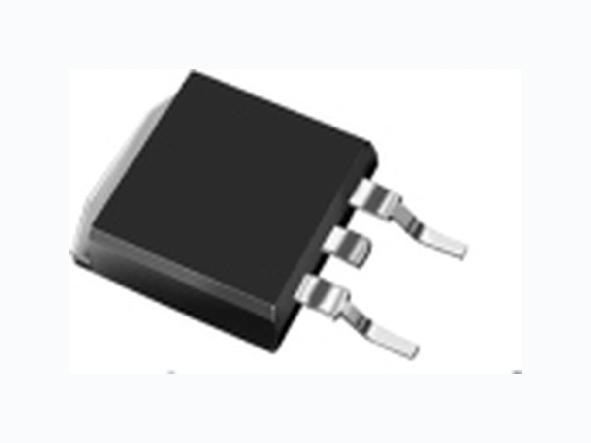
SR10100LD1 JINGHENG
Document overview
- Manufacturer or author: Provided By www.digicamel.com(FREE DATASHEET DOWNLOAD SITE)
- PDF pages: 4
Technical content
R SR10100LCT,SRF10100LCT,SR10100LD1,SR10100LM1 LOW VF SCHOTTKY BARRIER RECTIFIER Reverse Voltage - 100 Volts Forward Current - 10.0Amperes MAXIMUM RATINGS (Ratings at 25℃ ambient temperature unless otherwise specified ) S E M I C O N D U C T O R JINAN JINGHENG ELECTRONICS CO., LTD. HTTP://WWW.JINGHENGGROUP.COM4-1
FEATURES
Metal silicon junction ,majority carrier conduction Guard ring for overvoltage protection Low power loss ,high efficiency High current capability ,low forward voltage drop High forward surge capability High frequency operation Meets MSL Level 1,per J-STD-020,LF MAX peak of 245℃(for TO-263,252 package) Solder bath temperature 275℃ maximum,10s,per JESD22-B10 (for TO-220AB and ITO-220AB package) Component in accordance to RoHS 2011/65/EU PbPb RoHS COMPLIANT TYPICAL APPLICATIONS For use in low voltage ,high frequency inverters ,DC/DC converters,free wheeling ,and polarity protection applications Case: JEDEC TO-220AB、ITO-220AB、TO-263、TO-252 Molding compound meets UL94V-0 flammability rating Terminals: Lead solderable per J-STD-002 and JESD22-B102 Polarity: As marked Mounting Torque: 10 in-Ibs maximum JF SRF10100CT JF R S TO-220AB ITO-220AB Pin1 Pin3 Pin2 CA ES JF SR10100LCT 1 2 3 1 2 3 Pin1 Pin3 Pin2 Pin1 Pin2 K HEATSINK SR10100LCT SRF10100LCT SR10100LD1 TO-263 PRIMARY CHARACTERISTICS IF(AV) VRRM IFSM VF at IF=5.0A(125℃) TJ(MAX) 2×5A 100V 150A 150℃ 0.59V IR 10μA Package TO-220AB,ITO-220AB, TO-263,TO-252 Diode variations Common cathode JF SR 0100L M SR10100LM1 TO-252 Pin1 Pin2 K HEATSINK 1 1 2 2 K K Maximum repetitive peak reverse voltage VRRM A A IF(AV) IFSM ,TstgTJ Maximum average forward rectified current (see fig.1) Operating junction and Storage temperature range Peak forward surge current 8.3ms single half sine-wave superimposed on rated load (JEDEC method at rated TL) 5.0 150 -55 to+150 ℃ 100 Symbol UnitSR10100LCT, SRF10100LCT, SR10100LD1,SR10100LM1Parameter 10.0 Per leg Total device V Isolation voltage(ITO-220AB only)from terminals to heatsink t=1 min VAC 1500 V Peak repetitive reverse current per diode at tp=2μs 1KHz IRRM 0.5 A
ELECTRICAL CHARACTERISTCS(TA=25℃ Unless otherwise noted) Notes: 1.Pulse test: 300 μs pulse width,1% duty cycle 2.Pulse test: pulse width≤40ms THERMAL CHARACTERISTCS(TA=25℃ Unless otherwise noted) JINAN JINGHENG ELECTRONICS CO., LTD. HTTP://WWW.JINGHENGGROUP.COM4-2 RATINGS AND CHARACTERISTIC OF SR10100LCT,SRF10100LCT,SR10100LD1,SR10100LM1 Parameter Test Conditions Symbol TYP. MAX. Unit Instaneous forward voltage IF=5.0A TA=25℃ TA=100℃ ReVerse Current VR=100V TA=25℃ TA=100℃ VF IR 0.65 0.70 V 10 50 μA mA 2 5 Typical junction capacitance 4V,1MHz CJ pF TA=125℃ TA=125℃ 0.59 0.62 - 10 20 370 TA=25℃ TA=100℃ TA=125℃ IF=3.0A 0.55 0.53 0.51 0.60 Per Leg Per Leg AVAILABALE PACK INFORMATION Package Carton SizeL×W×H(mm)Quantity(pcs/box)Box Size L×W×H(mm) Quantity(box/carton) P/T 565×225×1701000558×148×38 5 Product code SR10100LCT-TO-220AB 3.Thermal resistance from junction to case Typical thermal resistance R JC 2.5 ℃/W3) 4.5 P/T 565×225×1701000558×148×38 5SRF10100LCT-ITO-220AB Parameter Symbol UnitSR10100LCT SRF10100LCT SR10100LD1 2.5 P/TSR10100LD1-TO-263 565×225×1701000558×148×38 5 SR10100LM1 2.5 P/T 565×225×1704000558×148×38 5SR10100LM1-TO-252
0.01 0.01 0.1 100 200 0.1 100 125 150 200 40 60 80 100 1 10 100 0 20 40 60 80 100 120 150 4.0 6.0 8.0 10.0 2.0 FIG.1-FORWARD CURRENT DERATING CURVE FIG.2-MAXIMUM NON-REPETITIVE PEAK FORWARD SURGE CURRENT FIG.3-TYPICAL INSTANTANEOUS FORWARD CHARACTERISTICS FIG.4-TYPICAL REVERSE CHARACTERISTICS AVERAGE FORWARD CURRENT AMPERES INSTANTANEOUS FORWARD CURRENT( AMPERES) INSTANTANEOUS REVERSE CURRENT (mA) PEAK FORWARD SURGE CURRENT(AMPERES) INSTANTANEOUS FORWARD VOLTAGE (V) PERCENT OF RATED PEAK REVERSE VOLTAGE% NUMBER OF CYCLES AT 60Hz CASE TEMPERATURE ( ℃) TJ=125℃TJ=125℃ PULSE WIDTH=300μS 1% DUTY CYCLE TJ=TJMAX 8.3ms SINGLE HALF SINE-WAVE (JEDEC Method) TJ=25℃ RESISTIVE OR INDUCTIVE LOAD FIG.5-TYPICAL JUNCTION CAPACITANCE TJ=100℃ TJ=125℃ JINAN JINGHENG ELECTRONICS CO., LTD. HTTP://WWW.JINGHENGGROUP.COM4-3 REVERSE VOLTAGE. VOLTS 0.1 1 10 100 100 4000 1000 JUNCTION CAPACITANCE(pF) TJ=25℃TJ=25℃ TJ=100℃TJ=100℃ 140 RATINGS AND CHARACTERISTIC OF SR10100LCT,SRF10100LCT,SR10100LD1,SR10100LM1 SR10100LCT SR10100LD1 SR10100LM1 SRF10100LCT
Dimensions in inches and (millimeters) TO-220AB 0.159(4.05) 0.105(2.67) 0.208(5.28) 0.037(0.94) 0.114(2.90) 0.161(4.10) 0.055(1.39) 0.185(4.70) 0.283(7.20) 0.560(14.22) 0.023(0.58) 0.138(3.50) 0.095(2.41) 0.192(4.88) 0.027(0.68) 0.102(2.60) 0.147(3.74) DIA 0.045(1.14) 0.175(4.44) 0.244(6.20) 0.516(13.10) 0.014(0.35) 0.410(10.41) PIN 0.390(9.91) 1 2 3 1.161(29.50) 1.106(28.10) 0.053(1.34) 0.047(1.20) 0.114(2.90) 0.098(2.50) ITO-220AB 0.104(2.64) 0.029(0.73) 0.111(2.83) 0.140(3.55) 0.110(2.80) 0.187(4.75) 0.272(6.90) 0.551(14.00) 0.029(0.73) 0.096(2.44) 0.019(0.47) 0.101(2.57) 0.128(3.25) DIA 0.102(2.60) 0.167(4.25) 0.256(6.50) 0.512(13.00) 0.019(0.47) PIN 1 2 3 0.130(3.31) 0.111(2.81) 0.056(1.43) 0.043(1.10) 0.410(10.41) 0.390(9.91) 0.067(1.70) 0.059(1.50) 0.190(4.83) 1 2K 0.380(9.65) 0.420(10.67) 0.245(6.22) MIN 0.560(14.22) 0.639(16.22) 0.027(0.69) 0.037(0.94) 0.095(2.41) 0.083(2.10) 0.320(8.13) 0.360(9.14) 0.090(2.29) 0.131(3.32) 0.134(3.40) 0.105(2.67) 0.018(0.46) 0.014(0.35) 0.045(1.14) 0.055(1.40) 0.036(0.92) 0.066(1.68) 0.160(4.06) 0.047(1.20) 0.053(1.34) PACKAGE OUTLINE DIMENSIONS JINAN JINGHENG ELECTRONICS CO., LTD. HTTP://WWW.JINGHENGGROUP.COM4-4 TO-263 1 2K 0.265(6.73) 0.244(6.20) 0.403(10.24) 0.354(9.00) 0.245(6.22) 0.220(5.60) 0.026(0.66) 0.018(0.46) 0.215(5.46) 0.205(5.21) 0.104(2.65) 0.085(2.15) 0.023(0.58) 0.017(0.42) 0.050(1.27) 0.035(0.88) 0.023(0.58) 0.017(0.42) 0.039(1.00) MIN. 0.084(2.14) 0.094(2.40) TO-252 0.42(10.67)MIN 0.560(14.22) 0.639(16.22) 0.095(2.41) 0.083(2.10) 0.08(1.032)MIN 0.15(3.81)MIN Suggested Pad Layout (TO-263) 0.265(6.73)MIN 0.094(2.40) 0.084(2.14) 0.08(1.032)MIN 0.080(2.00)MIN Suggested Pad Layout (TO-252) 0.354(9.00) 0.403(10.24)