
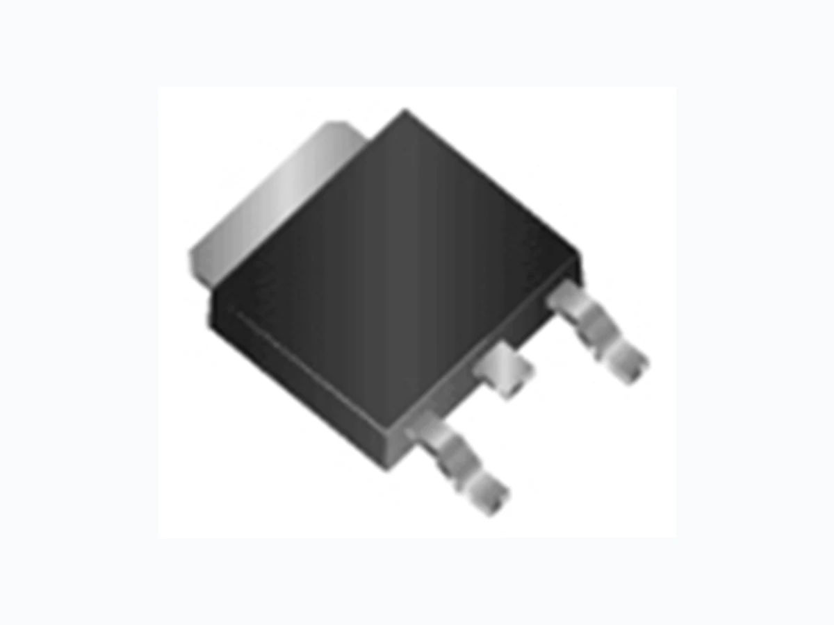
RCD100N19 ROHM
Document overview
- Manufacturer or author: Provided By www.digicamel.com(FREE DATASHEET DOWNLOAD SITE)
- PDF pages: 14
Technical content
www.rohm.com © 2015 ROHM Co., Ltd. All rights reserved. RCD100N19 Nch 190V 10A Power MOSFET Outline VDSS 190V CPT3 (SC-63) <SOT-428> RDS(on) (Max.) 182m ID 10A PD 85W Features Inner circuit 1) Low voltage drive (4V drive). 2) Low on-resistance. 3) Fast switching speed. 4) Drive circuits can be simple. 5) Parallel use is easy. 6) Pb-free lead plating ; RoHS compliant Packaging specifications 7) 100% Avalanche tested Type Packaging Taping Application Reel size (mm) 330 Switching Power Supply Tape width (mm) 16 Automotive Motor Drive Basic ordering unit (pcs) 2,500 Drain - Source voltage V DSS 190 V Automotive Solenoid Drive Taping code TL Marking C10N19 Absolute maximum ratings(Ta = 25°C) Parameter Symbol Value Unit Pulsed drain current ID,pulse *2 40 A Tc = 25°C Tc = 100°C Continuous drain current ID *1 A10 ID *1 5.4 A PD 0.85 W Avalanche energy, single pulse Avalanche current T c = 25°C Ta = 25°C *4Power dissipation Gate - Source voltage VGSS 20 V PD 85 W mJ A EAS *3 IAR *3 8.33 5.0 Junction temperature Tj 150 °C Range of storage temperature Tstg 55 to 150 °C 1 BODY DIODE (1) Gate (2) Drain (3) Source (1) (2) (3) (1) (2) (3) 1/12 2016.02 - Rev.B Not Recommended for New Designs
www.rohm.com © 2015 ROHM Co., Ltd. All rights reserved. Data Sheet RCD100N19 Thermal resistance, junction - case -1 0 - 100 Values Min. Typ. Max. Drain - Source breakdown voltage Zero gate voltage drain current V(BR)DSS IDSS V DS = 190V, VGS = 0V Tj = 25°C VDS = 190V, VGS = 0V VGS = 0V, ID = 1mA Thermal resistance Parameter Symbol Symbol Conditions Tsold Thermal resistance, junction - ambient *4 Soldering temperature, wavesoldering for 10s RthJA RthJC Electrical characteristics(Ta = 25°C) Parameter Values Unit Min. Typ. Max. - 1.46 °C/W - - °C/W147 V190 - - - - 265 Unit 100 nA Tj = 125°C VGate threshold voltage VGS (th) VDS = 10V, ID = 1mA 0.5 - 2.5 Gate - Source leakage current IGSS VGS = 20V, VDS = 0V -- S Static drain - source on - state resistance VGS = 10V, ID = 5.0A - 130 182 - 195 gfs VGS = 4.0V, ID = 5.0A 275 RDS(on) Forward transfer admittance VDS = 10V, ID = 5.0A 6 VGS = 10V, ID = 5.0A Tj = 125°C - 136 190 2/12 2016.02 - Rev.B Not Recommended for New Designs
www.rohm.com © 2015 ROHM Co., Ltd. All rights reserved. Data Sheet RCD100N19 *1 Limited only by maximum temperature allowed. *2 Pw 10s, Duty cycle 1% *3 L ⋍ 500H, VDD = 50V, Rg = 25, starting Tj = 25°C *4 Mounted on a epoxy PCB FR4 (20mm × 30mm × 0.8mm) *5 Pulsed Continuous source current 52 - I S = 5.0A di/dt = 100A/sReverse recovery charge Qrr *5 - 255 - Body diode electrical characteristics (Source-Drain)(Ta = 25°C) Parameter Symbol Conditions Values Unit Min. Typ. Max. Gate plateau voltage V(plateau) VDD ⋍ 100V, ID = 10A -2 . 5 nC 40 A Forward voltage VSD *5 VGS = 0V, IS = 10A -- 1 . 5 V 95 - ns Tc = 25°C Reverse recovery time trr IS *1 -- 1 0 A Pulsed source current ISM *2 - Electrical characteristics(Ta = 25°C) Parameter Symbol Conditions Values Unit Min. Typ. Max. pFOutput capacitance Coss VDS = 25V -9 5- Reverse transfer capacitance Crss f = 1MHz Input capacitance Ciss VGS = 0V - 2000 - -6 0- Turn - on delay time td(on) *5 VDD ⋍ 100V, VGS = 10V -1 5- ns Rise time tr *5 ID = 5.0A -2 0- Turn - off delay time td(off) Fall time tf *5 RG = 10 -7 5- Gate Charge characteristics(Ta = 25°C) Parameter Symbol Conditions Values Unit Min. Typ. Max. ID = 10A VGS = 10V -5- Gate - Drain charge Qgd *5 -1 1- nCGate - Source charge Qgs Total gate charge Qg *5 VDD ⋍ 100V - 3/12 2016.02 - Rev.B Not Recommended for New Designs
www.rohm.com © 2015 ROHM Co., Ltd. All rights reserved. Data Sheet RCD100N19 Electrical characteristic curves 100 120 0 25 50 75 100 125 150 175 0.01 0.1 0.0001 0.01 1 100 top D = 1 D = 0.5 D = 0.1 D = 0.05 D = 0.01 D = Single Ta=25ºC Single Pulse Rth(j-c)(t) = r(t)×Rth(ch-c) Rth(j-c) = 147ºC/W 0.01 0.1 100 0.1 1 10 100 1000 Ta=25ºC Single Pulse PW = 100s Operation in this area is limited by RDS(on) PW = 1ms PW = 10ms Fig.1 Power Dissipation Derating Curve Fig.2 Maximum Safe Operating Area Power Dissipation : PD/PD max. [%] Drain Current : ID [A] Fig.3 Normalized Transient Thermal Resistance vs. Pulse Width Normalized Transient Thermal Resistance : r(t) Pulse Width : PW [s] Junction Temperature : Tj [°C] Drain - Source Voltage : VDS [V] 4/12 2016.02 - Rev.B Not Recommended for New Designs
www.rohm.com © 2015 ROHM Co., Ltd. All rights reserved. Data Sheet RCD100N19 Electrical characteristic curves 0.5 1.5 2.5 0 0.2 0.4 0.6 0.8 1 VGS=2.0V Ta=25ºC PulsedVGS=10.0V VGS=4.0V VGS=4.5V VGS=2.5V VGS=3.0V 02468 1 0 VGS=2.0V Ta=25ºC Pulsed VGS=10.0V VGS=4.0V VGS=4.5V VGS=2.8V VGS=3.0V 0.1 100 0.01 0.1 1 10 100 VDD=50V,RG=25 VGF=10V,VGR=0V Starting Tch=25ºC 100 120 0 25 50 75 100 125 150 175 Fig.6 Typical Output Characteristics(I) Drain Current : ID [A] Drain - Source Voltage : VDS [V] Fig.7 Typical Output Characteristics(II) Drain Current : ID [A] Drain - Source Voltage : VDS [V] Fig.4 Avalanche Current vs Inductive Load Avalanche Current : IAS [A] Coil Inductance : L [mH] Fig.5 Avalanche Energy Derating Curve vs Junction Temperature Avalanche Energy : EAS / EAS max. [%] Junction Temperature : Tj [°C] 5/12 2016.02 - Rev.B Not Recommended for New Designs
www.rohm.com © 2015 ROHM Co., Ltd. All rights reserved. Data Sheet RCD100N19 Electrical characteristic curves 150 160 170 180 190 200 210 220 230 240 250 -50 0 50 100 150 VGS = 0V ID = 1mA 0.001 0.01 0.1 100 012345 VDS= 10V Ta= 125ºC Ta= 75ºC Ta= 25ºC Ta= 25ºC 0.0 0.5 1.0 1.5 2.0 2.5 3.0 -50 -25 0 25 50 75 100 125 150 VDS = 10V ID = 1mA 0.01 0.1 100 0.01 0.1 1 10 100 VDS= 10V Ta= 25ºC Ta=25ºC Ta=75ºC Ta=125ºC Fig.10 Gate Threshold Voltage vs. Junction Temperature Gate Threshold Voltage : VGS(th) [V] Junction Temperature : Tj [°C] Fig.11 Transconductance vs. Drain Current Transconductance : gfs [S] Drain Current : ID [A] Fig.8 Breakdown Voltage vs. Junction Temperature Junction Temperature : Tj [°C] Fig.9 Typical Transfer Characteristics Gate - Source Voltage : VGS [V] Drain Current : ID [A] Normarize Drain - Source Breakdown Voltage : V(BR)DSS [V] 6/12 2016.02 - Rev.B Not Recommended for New Designs
www.rohm.com © 2015 ROHM Co., Ltd. All rights reserved. Data Sheet RCD100N19 Electrical characteristic curves 100 150 200 250 300 0 5 10 15 Ta=25ºC ID = 10A ID = 5A 100 1000 0.01 0.1 1 10 100 Ta=25ºC VGS= 10V VGS= 4.0V 100 150 200 250 -50 0 50 100 150 VGS = 10V ID = 5A Fig.13 Static Drain - Source On - State Resistance vs. Drain Current(I) Static Drain - Source On-State Resistance : RDS(on) [m] Junction Temperature : Tj [ºC] Fig.14 Static Drain - Source On - State Resistance vs. Junction Temperature Static Drain - Source On-State Resistance : RDS(on) [m] Drain Current : ID [A] Fig.12 Static Drain - Source On - State Resistance vs. Gate Source Voltage Static Drain - Source On-State Resistance : RDS(on) [m] Gate - Source Voltage : VGS [V] 7/12 2016.02 - Rev.B Not Recommended for New Designs
www.rohm.com © 2015 ROHM Co., Ltd. All rights reserved. Data Sheet RCD100N19 Electrical characteristic curves 100 1000 0.01 0.1 1 10 100 Ta=125ºC Ta=75ºC Ta=25ºC Ta= 25ºC VGS= 10V 100 1000 0.01 0.1 1 10 100 Ta=125ºC Ta=75ºC Ta=25ºC Ta= 25ºC VGS= 4.0V 100 120 0 25 50 75 100 125 150 175 Fig.15 Static Drain - Source On - State Resistance vs. Drain Current(II) Static Drain - Source On-State Resistance : RDS(on) [m] Drain Current : ID [A] Fig.17 Drain Current Derating Curve Drain Current Dissipation : ID/ID max. (%) Junction Temperature : Tj [°C] Fig.16 Static Drain - Source On - State Resistance vs. Drain Current(III) Static Drain - Source On-State Resistance : RDS(on) [m] Drain Current : ID [A] 8/12 2016.02 - Rev.B Not Recommended for New Designs
www.rohm.com © 2015 ROHM Co., Ltd. All rights reserved. Data Sheet RCD100N19 Electrical characteristic curves 100 1000 10000 100000 0.01 0.1 1 10 100 1000 Coss Crss Ciss Ta=25ºC f=1MHz VGS=0V 100 1000 10000 0.01 0.1 1 10 100 tr tf td(on) td(off) Ta=25ºC VDD= 100V VGS= 10V RG=10 0 5 10 15 20 25 30 35 40 45 50 55 60 Ta=25ºC VDD= 100V ID= 10A RG=10 Fig.18 Typical Capacitance vs. Drain - Source Voltage Capacitance : C [pF] Drain - Source Voltage : VDS [V] Fig.20 Dynamic Input Characteristics Gate - Source Voltage : VGS [V] Total Gate Charge : Qg [nC] Fig.19 Switching Characteristics Switching Time : t [ns] Drain Current : ID [A] 9/12 2016.02 - Rev.B Not Recommended for New Designs
www.rohm.com © 2015 ROHM Co., Ltd. All rights reserved. Data Sheet RCD100N19 Electrical characteristic curves 100 1000 0.1 1 10 100 Ta=25ºC di / dt = 100A / s VGS = 0V 0.01 0.1 100 0.0 0.5 1.0 1.5 VGS=0V Ta=125ºC Ta=75ºC Ta=25ºC Ta= 25ºC Fig.21 Source Current vs. Source - Drain Voltage Source Current : IS [A] Source-Drain Voltage : VSD [V] Fig22 Reverse Recovery Time vs.Source Current Reverse Recovery Time : trr [ns] Source Current : IS [A] 10/12 2016.02 - Rev.B Not Recommended for New Designs
www.rohm.com © 2015 ROHM Co., Ltd. All rights reserved. Data Sheet RCD100N19 Measurement circuits Fig.1-1 Switching Time Measurement Circuit Fig.1-2 Switching Waveforms Fig.2-1 Gate Charge Measurement Circuit Fig.2-2 Gate Charge Waveform Fig.3-1 Avalanche Measurement Circuit Fig.3-2 Avalanche Waveform VGS IG(Const.) VDS D.U.T. ID RL VDD 90% 90% 90% 10% 10% 50% 10% 50% VGS Pulse width VDS ton toff trtd(on) tftd(off) VGS RG VDS D.U.T. ID RL VDD VG VGS Charge Qg Qgs Qgd VGS RG VDS D.U.T. IAS L VDD IAS VDD V(BR)DSS IAS LEAS = V(BR)DSS - VDD V(BR)DSS1 11/12 2016.02 - Rev.B Not Recommended for New Designs
www.rohm.com © 2015 ROHM Co., Ltd. All rights reserved. Data Sheet RCD100N19 Dimensions (Unit : mm) Dimension in mm/inches CPT3 D e b H A1 c Lp x BA L E L2 l2 l1 b5e BA MINM AXM INM AX A1 0.00 0.15 0 0.006 A2 2.20 2.50 0.087 0.098 b 0.55 0.75 0.022 0.03 b1 5.00 5.30 0.197 0.209 c 0.40 0.60 0.016 0.024 c1 0.40 0.60 0.016 0.024 D 6.30 6.70 0.248 0.264 E 5.40 5.80 0.213 0.228 e HE 9.00 10.00 0.354 0.394 L 2.20 2.80 0.087 0.11 L1 0.80 1.40 0.031 0.055 L2 1.20 1.80 0.047 0.071 Lp 1.00 1.60 0.039 0.063 x - 0.25 - 0.01 M I NM A XM I NM A X b5 - 1.00 - 0.04 b6 - 5.20 - 0.205 l1 - 2.50 - 0.098 l2 - 5.50 - 0.217 l3 - 10.00 - 0.394 0.90 0.035 0.25 0.01 2.30 0.09 5.30 0.209 DIM MILIMETERS INCHES DIM MILIMETERS INCHES 5.00 0.20 0.75 0.03 12/12 2016.02 - Rev.B Not Recommended for New Designs
Notice-PGA-E Rev.003 © 2015 ROHM Co., Ltd. All rights reserved. Notice Precaution on using ROHM Products 1. Our Products are designed and manufactured for application in ordinary electronic equipments (such as AV equipment, OA equipment, telecommunication equipment, home electronic appliances, amusement equipment, etc.). If you intend to use our Products in devices requiring extremely high reliability (such as medical equipment (Note 1), transport equipment, traffic equipment, aircraft/spacecraft, nuclear power controllers, fuel controllers, car equipment including car accessories, safety devices, etc.) and whose malfunction or failure may cause loss of human life, bodily injury or serious damage to property ( “Specific Applications”), please consult with the ROHM sales representative in advance. Unless otherwise agreed in writing by ROHM in advance, ROHM shall not be in any way responsible or liable for any damages, expenses or losses incurred by you or third parties arising from the use of any ROHM’s Products for Specific Applications. (Note1) Medical Equipment Classification of the Specific Applications JAPAN USA EU CHINA CLASSⅢ CLASSⅢ CLASSⅡb CLASSⅢ CLASSⅣ CLASSⅢ 2. ROHM designs and manufactures its Products subject to strict quality control system. However, semiconductor products can fail or malfunction at a certain rate. Please be sure to implement, at your own responsibilities, adequate safety measures including but not limited to fail-safe design against the physical injury, damage to any property, which a failure or malfunction of our Products may cause. The following are examples of safety measures: [a] Installation of protection circuits or other protective devices to improve system safety [b] Installation of redundant circuits to reduce the impact of single or multiple circuit failure 3. Our Products are designed and manufactured for use under standard conditions and not under any special or extraordinary environments or conditions, as exemplified below. Accordingly, ROHM shall not be in any way responsible or liable for any damages, expenses or losses arising from the use of any ROHM’s Products under any special or extraordinary environments or conditions. If you intend to use our Products under any special or extraordinary environments or conditions (as exemplified below), your independent verification and confirmation of product performance, reliability, etc, prior to use, must be necessary: [a] Use of our Products in any types of liquid, including water, oils, chemicals, and organic solvents [b] Use of our Products outdoors or in places where the Products are exposed to direct sunlight or dust [c] Use of our Products in places where the Products are exposed to sea wind or corrosive gases, including Cl2, H2S, NH3, SO2, and NO2 [d] Use of our Products in places where the Products are exposed to static electricity or electromagnetic waves [e] Use of our Products in proximity to heat-producing components, plastic cords, or other flammable items [f] Sealing or coating our Products with resin or other coating materials [g] Use of our Products without cleaning residue of flux (even if you use no-clean type fluxes, cleaning residue of flux is recommended); or Washing our Products by using water or water-soluble cleaning agents for cleaning residue after soldering [h] Use of the Products in places subject to dew condensation 4. The Products are not subject to radiation-proof design. 5. Please verify and confirm characteristics of the final or mounted products in using the Products. 6. In particular, if a transient load (a large amount of load applied in a short period of time, such as pulse. is applied, confirmation of performance characteristics after on-board mounting is strongly recommended. Avoid applying power exceeding normal rated power; exceeding the power rating under steady-state loading condition may negatively affect product performance and reliability. 7. De-rate Power Dissipation depending on ambient temperature. When used in sealed area, confirm that it is the use in the range that does not exceed the maximum junction temperature. 8. Confirm that operation temperature is within the specified range described in the product specification. 9. ROHM shall not be in any way responsible or liable for failure induced under deviant condition from what is defined in this document. Precaution for Mounting / Circuit board design 1. When a highly active halogenous (chlorine, bromine, etc.) flux is used, the residue of flux may negatively affect product performance and reliability. 2. In principle, the reflow soldering method must be used on a surface-mount products, the flow soldering method must be used on a through hole mount products. I f the flow soldering method is preferred on a surface-mount products , please consult with the ROHM representative in advance. For details, please refer to ROHM Mounting specification Not Recommended for New Designs
Notice-PGA-E Rev.003 © 2015 ROHM Co., Ltd. All rights reserved. Precautions Regarding Application Examples and External Circuits 1. If change is made to the constant of an external circuit, please allow a sufficient margin considering variations of the characteristics of the Products and external components, including transient characteristics, as well as static characteristics. 2. You agree that application notes, reference designs, and associated data and information contained in this document are presented only as guidance for Products use. Therefore, in case you use such information, you are solely responsible for it and you must exercise your own independent verification and judgment in the use of such information contained in this document. ROHM shall not be in any way responsible or liable for any damages, expenses or losses incurred by you or third parties arising from the use of such information. Precaution for Electrostatic This Product is electrostatic sensitive product, which may be damaged due to electrostatic discharge. Please take proper caution in your manufacturing process and storage so that voltage exceeding the Products maximum rating will not be applied to Products. Please take special care under dry condition (e.g. Grounding of human body / equipment / solder iron, isolation from charged objects, setting of Ionizer, friction prevention and temperature / humidity control). Precaution for Storage / Transportation 1. Product performance and soldered connections may deteriorate if the Products are stored in the places where: [a] the Products are exposed to sea winds or corrosive gases, including Cl2, H2S, NH3, SO2, and NO2 [b] the temperature or humidity exceeds those recommended by ROHM [c] the Products are exposed to direct sunshine or condensation [d] the Products are exposed to high Electrostatic 2. Even under ROHM recommended storage condition, solderability of products out of recommended storage time period may be degraded. It is strongly recommended to confirm solderability before using Products of which storage time is exceeding the recommended storage time period. 3. Store / transport cartons in the correct direction, which is indicated on a carton with a symbol. Otherwise bent leads may occur due to excessive stress applied when dropping of a carton. 4. Use Products within the specified time after opening a humidity barrier bag. Baking is required before using Products of which storage time is exceeding the recommended storage time period. Precaution for Product Label A two-dimensional barcode printed on ROHM Products label is for ROHM’s internal use only. Precaution for Disposition When disposing Products please dispose them properly using an authorized industry waste company. Precaution for Foreign Exchange and Foreign Trade act Since concerned goods might be fallen under listed items of export control prescribed by Foreign exchange and Foreign trade act, please consult with ROHM in case of export. Precaution Regarding Intellectual Property Rights 1. All information and data including but not limited to application example contained in this document is for reference only. ROHM does not warrant that foregoing information or data will not infringe any intellectual property rights or any other rights of any third party regarding such information or data. 2. ROHM shall not have any obligations where the claims, actions or demands arising from the combination of the Products with other articles such as components, circuits, systems or external equipment (including software). 3. No license, expressly or implied, is granted hereby under any intellectual property rights or other rights of ROHM or any third parties with respect to the Products or the information contained in this document. Provided, however, that ROHM will not assert its intellectual property rights or other rights against you or your customers to the extent necessary to manufacture or sell products containing the Products, subject to the terms and conditions herein. Other Precaution 1. This document may not be reprinted or reproduced, in whole or in part, without prior written consent of ROHM. 2. The Products may not be disassembled, converted, modified, reproduced or otherwise changed without prior written consent of ROHM. 3. In no event shall you use in any way whatso ever the Products and the related technical information contained in the Products or this document for any military purposes, including but not limited to, the development of mass-destruction weapons. 4. The proper names of companies or products described in this document are trademarks or registered trademarks of ROHM, its affiliated companies or third parties. Not Recommended for New Designs