
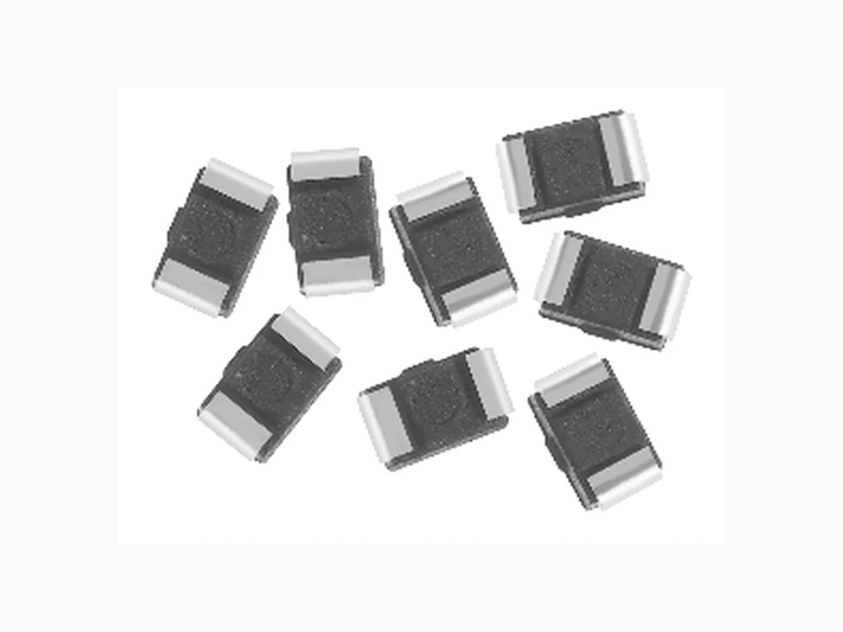
IMC-0805_07 VISHAY
Document overview
- Manufacturer or author: Provided By www.digicamel.com(free datasheet download site)
- PDF pages: 2
Technical content
High Frequency, Surface Mount, Molded Inductors www.vishay.com For technical question s, contact: magnetics@vishay.com Document Number: 34040 IMC-0805 Vishay Dale
FEATURES
- High self-resonant frequency values
- High Q values at higher frequencies
- Molded construction provides superior strength and moisture resistance
- Wirewound construction
- Tape and reel packaging for automatic handling, 3000/reel, EIA481
- Compatible with vapor phase and infrared reflow soldering
- 100 % lead (Pb)-free and RoHS compliant RoHS COMPLIANT NOTE: Tighter tolerance product may be substituted based on availability. STANDARD ELECTRICAL SPECIFICATIONS IND. (nH) TOL. TEST FREQ. L & Q (MHz) Q MIN. Q TYPICAL SELF- RESONANT FREQ. MIN. (MHz) DCR ± 30 % (Ohms) RATED* DC CURRENT (mA) 100 MHz 800 MHz 1.8 GHz ± 10 % ± 10 % ± 10 % ± 10 % ± 10 % 100 100 100 100 100 110 105 100 3300 3300 3000 3000 2600 0.14 0.18 0.18 0.22 0.22 540 535 520 480 465 ± 10 % ± 5 %, ± 10 % ± 5 %, ± 10 % ± 5 %, ± 10 % ± 5 %, ± 10 % 100 100 100 100 100 2500 2050 2000 1650 1550 0.26 0.30 0.31 0.35 0.39 455 395 390 385 360 100 120 150 ± 5 %, ± 10 % ± 5 %, ± 10 % ± 5 %, ± 10 % ± 5 %, ± 10 % ± 5 %, ± 10 % 100 100 25.2 25.2 25.2 1450 1100 800 600 600 0.44 0.48 0.66 0.76 1.13 340 330 285 275 230 180 220 270 330 390 ± 5 %, ± 10 % ± 5 %, ± 10 % ± 5 %, ± 10 % ± 5 %, ± 10 % ± 5 %, ± 10 % 25.2 25.2 25.2 25.2 25.2 600 500 300 200 150 1.24 1.41 1.50 1.66 1.82 195 170 165 160 150 470 560 680 820 1000 ± 5 %, ± 10 % ± 5 %, ± 10 % ± 5 %, ± 10 % ± 5 %, ± 10 % ± 5 %, ± 10 % 25.2 25.2 25.2 25.2 7.96 150 100 100 1.97 2.07 2.32 2.60 2.98 145 140 130 125 120 ELECTRICAL SPECIFICATIONS Inductance Range: 10 nH to 1000 nH Inductance Tolerance: ± 20 % for 3.9 nH to 8.2 nH ± 10 % for 6.8 nH to 1000 nH ± 5 % for 33 nH to 1000 nH Temperature Range: - 40 °C to + 105 °C (no load). - 40 °C to + 85 °C (at full rated current) Core Material: Non-magnetic TEST EQUIPMENT
- Inductance and Q measured on HP4191A
- SRF measured on HP8753B DIMENSIONS in inches [millimeters] GLOBAL PART NUMBER
DESCRIPTION
n H ± 5 % ER e3 MODEL I NDUCTANCE I NDUCTANCE PACKAGE JEDEC LEAD (Pb)-FREE VALUE TOLERA NCE CODE STA NDARD MODEL SIZE INDUCTANCE VALUE PACKAGE CODE TOL. IM C 0 8 05 ER I O N J 0.078 + 0.012 - 0.008 [2.00 + 0.3 - 0.2] 0.049 ± 0.012 [1.25 ± 0.3] 0.016 ± 0.008 [0.4 ± 0.2] 0.049 ± 0.012 [1.25 ± 0.3] 0.039 ± 0.004 [1.0 ± 0.1] Recommended Pad Layout 0.043 ± 0.004 [1.1 ± 0.1] 0.043 ± 0.008 [1.1 ± 0.2] 0.134 ± 0.016 [3.4 ± 0.4]
Document Number: 91000 www.vishay.com Revision: 08-Apr-05 1 Notice Specifications of the products displayed herein are subjec t to change without notice. Vishay Intertechnology, Inc., or anyone on its behalf, assumes no responsibility or liability for any errors or inaccuracies. Information contained herein is intended to provide a product description only. No license, express or implied, by estoppel or otherwise, to any intellectual property rights is granted by this document. Except as provided in Vishay's terms and conditions of sale for such products, Vishay assumes no liability whatsoever, and disclaims any express or implied warranty, relating to sale and/or use of Vishay products including liability or warranties relating to fitness for a particular purpose, merchantability, or infringement of any patent, copyright, or other intellectual property right. The products shown herein are not designed for use in medical, life-saving, or life-sustaining applications. Customers using or selling these products for use in such applications do so at their own risk and agree to fully indemnify Vishay for any damages resulting from such improper use or sale.