
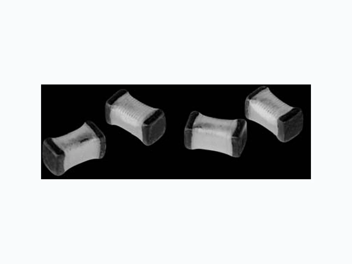
IMC-0402 VISHAY
Document overview
- Manufacturer or author: Provided By www.digicamel.com(FREE DATASHEET DOWNLOAD SITE)
- PDF pages: 1
Technical content
www.vishay.com IMC-0402 Vishay Dale Document Number 34038 Revision 16-May-03 For technical questions, contact Magnetics@vishay.com High Frequency, Surface Mount, Laser Spiral, Coated Inductors
FEATURES
- Very small in size
- High self-resonant frequency values
- High Q values relative to size at higher frequencies
- Coated coil provides protection and moisture resistance
- Compatible with vapor phase and infrared reflow soldering
- T ape and reel packaging for automatic handling, 10,000/reel, EIA-481
- L and Q value not affected by mounting orientation STANDARD ELECTRICAL SPECIFICATIONS ELECTRICAL SPECIFICATIONS Inductance Range: 1.0nH to 100nH Inductance and Tolerance:± 0.3nH for 1.0 - 5.6nH ± 5% for 6.8nH to 100nH Operating Temperature: - 40°C to + 100°C Core Material: Ceramic TEST EQUIPMENT
- Inductance and Q measured on HP4291B
- SRF measured on HP8753E
- DCR measured on HP4338B INDUCTANCE (nH) 1.0 ± 0.3nH, 0.2nH 100 21 800 6000 0.05 400 1.2 ± 0.3nH, 0.2nH 100 21 800 6000 0.06 400 1.5 ± 0.3nH, 0.2nH 100 21 800 6000 0.07 400 1.8 ± 0.3nH, 0.2nH 100 21 800 6000 0.08 400 2.2 ± 0.3nH, 0.2nH 100 21 800 6000 0.09 400 2.7 ± 0.3nH, 0.2nH 100 21 800 5500 0.10 400 3.3 ± 0.3nH, 0.2nH 100 21 800 5500 0.12 400 3.9 ± 0.3nH, 0.2nH 100 20 800 5200 0.15 360 4.7 ± 0.3nH, 0.2nH 100 20 800 4800 0.17 360 5.6 ± 0.3nH, 0.2nH 100 20 800 4600 0.19 340 6.8 ± 5% 100 19 800 4000 0.30 320 8.2 ± 5% 100 19 800 3500 0.35 320 10 ± 5%, 2% 100 19 800 2800 0.41 320 12 ± 5%, 2% 100 19 800 2800 0.45 320 15 ± 5%, 2% 100 19 800 2500 0.60 240 18 ± 5%, 2% 100 19 800 2200 0.70 240 22 ± 5%, 2% 100 19 800 2000 0.80 200 27 ± 5%, 2% 100 19 800 1800 1.20 200 33 ± 5%, 2% 100 18 800 1800 1.40 170 39 ± 5%, 2% 100 18 800 1800 1.70 150 47 ± 5%, 2% 100 17 800 1800 2.10 140 56 ± 5%, 2% 100 17 800 1500 2.50 130 68 ± 5%, 2% 100 15 800 1500 4.00 120 82 ± 5%, 2% 100 15 800 1400 4.50 110 100 ± 5%, 2% 100 14 800 1200 5.50 90 TOLERANCE TEST FREQUENCY L (MHz) Q TYPICAL TEST FREQUENCY Q (MHz) SELF-RESONANT FREQUENCY MINIMUM (MHz) DCR MAXIMUM (Ohms) RATED DC* CURRENT (mA) DIMENSIONS in inches [millimeters] 0.020 ± 0.004 Solder Pad Layout0.008 [0.2] 0.020 ± 0.004 [0.5 ± 0.1] 0.039 ± 0.004 [1.0 ± 0.1] 0.02 [0.50] 0.020 [0.50] 90/10 Sn/Pb TerminationDESCRIPTION IMC-0402 MODEL 10nH INDUCTANCE VALUE ± 5% INDUCTANCE TOLERANCE *Value obtained when current flows and temperature has risen 15°C SAP PART NUMBERING GUIDELINES (INTERNAL) PRODUCT FAMILY SIZE See the end of this data book for conversion tables INDUCTANCE VALUE PACKAGE CODE TOL. IM C 0 40 2 RK 10N J