
ESCP-MIS1 ES
Document overview
- Manufacturer or author: Provided By www.digicamel.com(FREE DATASHEET DOWNLOAD SITE)
- PDF pages: 19
Technical content
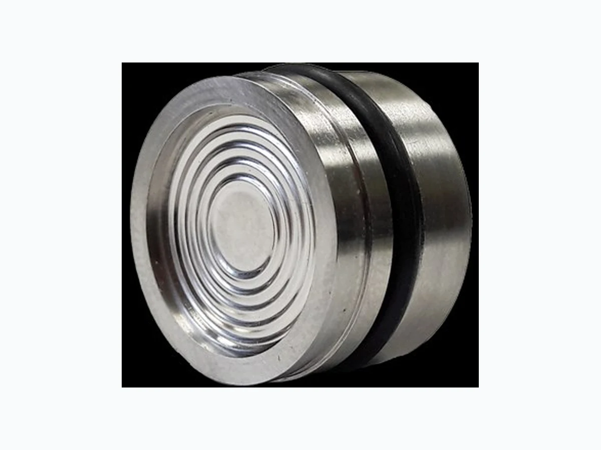
v1.6 Datasheet ESCP-MIS1 MEMS Capacitive Pressure & Temperature Sensor for gases & liquids. Product Summary ES Systems has developed a series of medium isolated pressure sensors suitable for applications with harsh environmental conditions where resistance to corrosive fluids or gases is required. Each sensor integrates a MEMS capacitive pressure sensor die, and a CMOS ASIC for the signal conditioning. The MEMS pressure sensor dies are underpinned by ES Systems ’ innovative microfabrication process for silicon capacitive sensors. The capacitive pressure sensor dies integrated into the medium isolated pressure systems provide state -of-the-art accuracy and resolution, excellent long -term stability combined with very good repeatability and hysteresis. The total overall error including thermal offsets is lower than ±0.25% FS. The ESCP-MIS1 is a family of pressure sensors in the standard Ø19 stainless steel 316L capsule. In this type of sensors, the pressure is transferred hydraulically to the hermetically sealed sensing element through the oil used to fill the cavity between the sensing element and the stainless steel diaphragm. The pressure capsule interface is either I 2C, SPI or analog. The sensors are provided calibrated and compensated at various temperature and pressure ranges from 10 bara to 350 bara. Custom materials like Hastelloy or Titanium are available upon request.
- State of the art performance due to MEMS capacitive technology
- Outstanding overpressure tolerance (up to 100x)
- Absolute operation
- Full scale pressure sensor options from 10 to 350 bar
- Temperature sensor: -40oC to +125oC
- Calibrated & temperature compensated output
- I2C, SPI or analog interface
- Excellent accuracy, resolution, long term stability
- Low power consumption
- No external components required Typical Applications
- Gas, Liquid Pressure Measurement
- Corrosive Fluids and Gas Measurement Systems
- Sealed Systems
- Manifold Pressure Measurement
- Submersible Depth Monitoring
- Medical Instruments
- Industrial Process Control
- Pressure Calibrator
- Pressure Transmitter Integration
- Refrigeration Equipment & Air Conditioner
- OEM equipment A ll data sheet.com
Total Error Band (TEB) is a single specification that includes all possible sources of error in a pressure measurement. TEB should not be confused with accuracy, which is actually a component of TEB. TEB is the worst error that the sensor could experience. The TEB specification on a datasheet may be confusing. ES Systems uses the TEB specification in its datasheet because it is the most comprehensive measurement of a sensor ’s true accuracy. ES Systems also provides the accuracy specification in order to provide a common comparison with competitors’ literature that does not use the TEB specification. Offset Full Scale Span Pressure Non-Linearity Pressure Hysteresis Noise Pressure Non-Repeatability Thermal Effect on Offset Thermal Effect on Span Thermal Hysteresis Accuracy TEB All Possible Errors Accuracy Performance Range: 10, 12, 13, 14, 18, 20, 28, 30, 35, 70, 100, 200, 350 bar 0% FS to 100%FS = ±0.125%FS Total Error Band Performance Range: 10, 12, 13, 14, 18, 20, 28, 30, 35, 70, 100, 0% FS to 100%FS = ±0.25%FS Range: 200, 350 bar 0% FS to 100%FS = ±0.5%FS The figure below, illustrates the accuracy as well as the total error of the pressure measurement of ESCP -MIS1 sensors. 1. Total Error Band A ll data sheet.com
- Absolute Maximum Ratings1 Characteristic Min. Max. Unit Supply voltage (Vsupply) 3.1 5.5 Vdc Voltage on any pin -0.3 5.5 V Current on any pin - 2 mA Burst pressure - 1000 bara Storage temperature -40[-40] +125[+257] oC[oF] Maximum pressure applied - 1000 bara 1 Absolute maximum ratings are the extreme limits the device will withstand without damage. The electrical and performance characteristics are not guaranteed as the maximum limits are approached, nor will the device necessarily operate as specified at absolute maximum ratings. Prolonged operation at absolute maximum ratings will degrade the device performance CAUTION IMPROPER HANDLE Do not touch the sensing membrane. Failure to comply with the instructions may result in product damage. CAUTION PRODUCT DAMAGE Do not disassemble these products. Failure to comply with the instructions may result in product damage. 3. Operating Specifications Characteristic Min. Typ. Max. Unit Supply voltage (Vsupply)1 3.1 3.3 5.5 V Supply current - - 2.3 mA Output Calibrated Pressure & Temperature - Output Interface I2C, SPI, Analog (0.5 to 2.5V) - Digital bus frequency - - 100 kHz SPI tsetup 100 150 1000 usec I2C/SPI voltage Level Low High %Vsupply Pull up on SDA / SCL 4.7 - - kOhm Analog Output Resistance 10k - - Ohm Start-up time2 - 30 - msec Operating temp. range -40[-40] - +125[+257] oC[oF] Relative humidity (non-condensing) - - 100 % RH Material Stainless Steal, Titanium, Hastelloy - Filling Oil Silicon, Food, Fluorinated Sealing type O-ring (FKM, EPDM, NBR, VMQ, HNBR), weld - Media Compatibility Gases, liquids - 1The sensor is not reverse polarity protected. Incorrect application of supply voltage or ground to the wrong pin may cause electrical failure. 2After 95% of Vsupply reached. A ll data sheet.com
- Pressure Sensor Specifications Characteristic Absolute Unit Min. Typ. Max. Pressure Type absolute - Pressure Range Up to 350 bara Full scale ranges 10, 12, 13, 14, 18, 20, 28, 30, 35, 70, 100, 200, 350 bara Compensated temp range1 Option 01 Option 02 Option 03 0[32] -20[-4] -40[-40] +60[+140] +85[+185] +125[+257] oC[oF] Effective Resolution Response Time (10Hz) Response Time (1kHz) bits Total error band2 < 100 bar 0 to +60 oC -20 to +85 oC -40 to +125 oC Total error band > 100 bar 0 to +60 oC -20 to +85 oC -40 to +125 oC ±0.25 ±0.25 ±0.25 ±0.5 ±0.5 ±0.5 %FS3 Accuracy4 - ±0.125 - %FS Long term stability5 - - ±0.25 %FSS6 1 The temperature range over which the sensor will produce an output proportional to pressure within the specified performance limits. Note that for valid datasheet values, ambient and medium temperatures must be the same 2 The maximum deviation from ideal transfer function over the entire compensated temperature and pressure range. Includes all errors due to offset, full scale span, accuracy, thermal effect on offset, thermal effect on span and thermal hysteresis 3 % of the full scale 4 The maximum deviation in output from a Best Fit Straight Line (BFSL) fitted to the output measured over the pressure range at 21oC [69.8oF]. Includes all errors due to pressure non-linearity, pressure hysteresis, non-repeatability and noise
5 Accelerated Life Test Profile: 100hours at 90oC
6 Full Scale Span (FSS): The algebraic difference between the output signal measured at the maximum (P max) and the minimum (Pmin) limits of the pressure range 5. Temperature Sensor Operating Specifications Characteristic Unit Min. Typ. Max. Full Scale range -40[-40] - +125[+257] oC[oF] Accuracy - 0.5 - oC Resolution 14 - - bits Output Rate - 250 - msec A ll data sheet.com
- Pressure Range Specifications Pressure Range Pressure Range Unit Proof Pressure1 Burst Pressure2 Pmin Pmax Port Port Absolute 010BA 0.25 10 bar 1000 1000 012BA 0.25 12 bar 1000 1000 013BA 0.25 13 bar 1000 1000 014BA 0.25 14 bar 1000 1000 018BA 0.5 18 bar 1000 1000 020BA 0.5 20 bar 1000 1000 028BA 0.5 28 bar 1000 1000 030BA 0.5 30 bar 1000 1000 035BA 0.5 35 bar 1000 1000 070BA 0.5 70 bar 1000 1000 100BA 1 100 bar 1000 1000 200BA 1 200 bar 1000 1000 350BA 1 350 bar 1000 1000 1 Overpressure: The maximum pressure which may safely be applied to the product for it to remain in specification once pressure is returned to the operating pressure range. Exposure to higher pressures may cause permanent damage to the product. Unless otherwise specified this applies to all available pressure ports at any temperature with the operat- ing temperature range 2 Burst pressure: The maximum pressure that may be applied to the specified port (P1 or P2) of the product without causing escape of pressure media. Product should not be expected to function after exposure to any pressure beyond the burst pressure Component Pressure Port Dry Gas or Liquid Media Material Stainless Steel 316L2 O-ring FKM3 Weight 17g 7. Wetted Matterials1
1 Contact ESS Customer Service for detailed material information
2 Titanium, Hastelloy are also available
3 EPDM, NBR, VMQ, HNBR are also available
A ll data sheet.com
- Data & Register Description The ESCP -MIS1 sensors provide measurement and status data. The measurement data are Pressure and Temperature. The data are stored in specific data registers as described below. The readout is performed by using multibyte read transactions. Both I 2C and SPI communication share the same structure. First byte is the register address which defines the appropriate register to be written/read and then follows the payload in either direction. The difference between the two serial interfaces is that in I 2C version the user need to address ESCP-MIS1 device and confirm each byte reception/transmit by receiving an ack after each transaction. Result Registers [0x0X] ADDRESS REGISTER NAME TYPE DEFAULT VALUE (Hex) MNEMONIC 0x01 Calibrated Pressure Byte 1 R Variable CAL_PRESS_DATA[31:24] Calibrated Pressure Byte 2 R Variable CAL_PRESS_DATA[23:16] Calibrated Pressure Byte 3 R Variable CAL_PRESS_DATA[15:8] Calibrated Pressure Byte 4 R Variable CAL_PRESS_DATA[7:0] Address 0x01 holds the pressure result in bars. The lowest and highest value depends on the pressure range of the sensor and cannot exceed the maximum range. Over and under pressure conditions are indicated in status register (see the corresponding register 0x13). An example of a pressure measurement is: Calibrated Pressure Byte 1 = 0x40 Calibrated Pressure Byte 2 = 0xAB Calibrated Pressure Byte 3 = 0x85 Calibrated Pressure Byte 4 = 0x1E After every conversion is completed, based on the programed rate and data output, ECSP - MIS1 sensor updates the corresponding data registers values. Data are in IEEE -754 floating point format (32bit) and are returned in MSB first sequence. A ll data sheet.com
The result is represented in the IEEE 754 format and any device that has a IEEE 754 compatible arithmetic unit does not need to convert it. IEEE 754 float format conversion: IEEE 754 format consists of 3 parts: the sign bit (bit 32), exponent part (bits 30:23), mantissa or fractional part (bits 22:0) as shown in the example above: The sign bit (s) represents the sign of the number and it is positive (+) for 0 and negative ( -) for 1. For the absolute value of the number we need to calculate the mantissa and the exponent part. The 8 bits of the exponent part are translated as an unsigned integer ranging from 0 to 255 with offset 127. For the mantissa part we need to calculate the above sum: After calculating the above the final result is given by the equation: In the example for 0x40AB851E (b0100 0000 1010 1011 1000 0101 0001 1110) we get: Sign = 0, Exponent = 129, Mantissa = 1.33999991417 Finally pressure measured is P = + 1.33999991417 X 2 130-127 = 5.36 bar Embedded software conversion: In practice, the user should just cast the received bytes from registers 0x0X to a float variable with IEEE 754 format and the calculations will be done automatically by the compiler. A ll data sheet.com
ADDRESS REGISTER NAME TYPE DEFAULT VALUE (Hex) MNEMONIC 0x02 Calibrated Temperature Byte 1 R Variable CAL_TEMP_DATA[31:24] Calibrated Temperature Byte 2 R Variable CAL_TEMP_DATA[23:16] Calibrated Temperature Byte 3 R Variable CAL_TEMP_DATA[15:8] Calibrated Temperature Byte 4 R Variable CAL_TEMP_DATA[7:0] Address 0x02 holds the temperature result in degrees Celsius . The conversion from IEEE 754 format is the same as for register 0x01. ADDRESS REGISTER NAME TYPE DEFAULT VALUE (Hex) MNEMONIC 0x00 Calibrated Pressure Byte 1 R Variable CAL_PRESS_DATA[31:24] Calibrated Pressure Byte 2 R Variable CAL_PRESS_DATA[23:16] Calibrated Pressure Byte 3 R Variable CAL_PRESS_DATA[15:8] Calibrated Pressure Byte 4 R Variable CAL_PRESS_DATA[7:0] Calibrated Temperature Byte 1 R Variable CAL_TEMP_DATA[31:24] Calibrated Temperature Byte 2 R Variable CAL_TEMP_DATA[23:16] Calibrated Temperature Byte 3 R Variable CAL_TEMP_DATA[15:8] Calibrated Temperature Byte 4 R Variable CAL_TEMP_DATA[7:0] Address 0x00 returns all available results sequentially. Reading register 0x00 equals reading sequentially the results at registers 0x01, 0x02 without having to start a new transaction. It is especially convenient when the user wants to read calibrated pressure and temperature on one I2C transaction. A ll data sheet.com
Info and Status registers [0x1X] The 0x1X registers set provides info for the specific device, firmware version and working status. Also provides the user the means to perform a software reset of the device. ADDRESS REGISTER NAME TYPE DEFAULT VALUE (Hex) MNEMONIC 0x10 Software reset - No payload - Addressing register 0x10 results in a software reset of the ESCP -MIS1 device right after the reception of the register address. This will reset the settings that the user programed during the last operation cycle and will return the device on its default state. ADDRESS REGISTER NAME TYPE DEFAULT VALUE (Hex) MNEMONIC 0x11 Product Family Code Byte 1 R Fixed ID PFC[7:0] Product Family Code Byte 2 R Fixed ID PFC[15:8] Product code Byte 1 R Fixed ID PC[7:0] Product code Byte 2 R Fixed ID PC[15:8] Lot number R Fixed ID LOT_NUMBER [7:0] Serial number 1 R Fixed ID SERIAL_NUMBER[7:0] Serial number 2 R Fixed ID SERIAL_NUMBER[15:8] Register 0x11 contains a unique, to every ESCP -MIS1 pressure sensor, serial number that consists of 4 parts: [Product Family Code] -[Product Code] [Lot number] -[Serial Number]. For example the serial number 0x8803530104001C translates to: 904-339 04-0028 A ll data sheet.com
ADDRESS REGISTER NAME TYPE DEFAULT VALUE (Hex) MNEMONIC 0x12 Fw version Major R Fixed version MAJOR_VER[7:0] Fw version Minor R Fixed version MINOR_VER[7:0] Fw version sub-Minor R Fixed version SUB_MINOR_VER[7:0] Register 0x12 contains the firmware version of the ESCP -MIS1 capsule. First Byte is the major version number, second number is the minor firmware version and the last Byte represents the sub minor firmware version. ADDRESS REGISTER NAME TYPE DEFAULT VALUE (Hex) MNEMONIC Status Register R Variable RUNNING_BIT[7:7] 0x13 RESERVED[6:2] UNDER_PRESSURE[1:1] OVER_PRESSURE[0:0] Register 0x13 returns the ESCP-MIS1 status vector. RUNNING_BIT : when the device ha started conversions the bit is 1. If the conversions are not started or the user has stopped the conversions then the bit is 0 UNDER_PRESSURE: when the pressure sensor is exposed in pressure under the rated pressure range the bit is set to 1 and the result is clipped. OVER_PRESSURE: when the pressure sensor is exposed in pressure over the rated pressure range the bit is set to 1 and the result is clipped. RESERVED: internal functionality should return 0 A ll data sheet.com
- I2C Interface At power on reset, the sensor needs 30ms to initialize. After that time the device is ready to communicate as an I2C slave device with 7-bit address 0x28. If the master device transmits the selected sensor 7-bit address (0x50) with R/W bit set, and the appropriate register address, the sensor returns the result specified in the previous section after acknowledging (ACK) by holding the SDA line low. In order for the master to receive the data requested, should send 8 clock pulses for each data byte and provide an acknowledge bit at the 9 th clock cycle by holding the SDA line low. When the last byte is received a stop condition is issued from the master indicating the termination of the transaction. An example of such a transaction is shown below. VDD GND 4k7 4k7 VDD MCU SENSOR SDA SCL I2C Read A ll data sheet.com
A typical use case is presented bellow. The user powers up the ESCP -MIS1 either by applying power to the system or by sending a reset command to the device. After initializing, the user reads the device ’s serial number and firmware version and reads the pressure and temperature values periodically. At any time the user can read the status register to check that the sensor is converting and the maximum or minimum pressure limit is not exceeded A ll data sheet.com
- SPI Interface MCU VDD GND SENSOR CS MOSI MISO SCLK SPI serial peripheral interface follows the same register mapping as described in section 8. The sensor uses mode 0 SPI with CPOL = 0 and CPHA = 0. The SPI communication requires to send, via the MOSI signal, the address to read and then the following clock pulses will produce the required result on the MISO line. After the address setting the slave requires a t setup time before issuing the data clock pulses in order to fetch the data to output buffer. The CS line should be driven low and kept low during the transaction. The following example describe the SPI transactions for reading the pressure output of the SPI Read A ll data sheet.com
A typical use case is presented bellow. The user powers up the ESCP -MIS1 either by applying power to the system or by sending a reset command to the device. After initializing, the user reads the device ’s serial number and firmware version and reads the pressure and temperature values periodically. At any time the user can read the status register to check that the sensor is converting and the maximum or minimum pressure limit is not exceeded. A ll data sheet.com
- Analog Interface The analog output of the sensor is updated at the default digital rate of 10Hz. The calibrated output is in the range of 0.5 - 2.5 VDC . The output resistance of the sensor is 10kOhms. The user must ensure that the input of the ADC is at high enough impedance to allow elimination of potential voltage division errors. GND SENSOR 3.0V INT REF 0.5-2.5V RangeADC 12. Pinouts2 Output PIN1 PIN2 PIN3 PIN4 PIN5 PIN6 I2C NC1 SDA SCL NC VDD GND SPI CS MOSI SCLK MISO VDD GND Analog NC NC NC AOUT VDD GND
1 Do not Connect
2 Electrical Connection: BM06B-SRSS-TB(LF)(SN)
Vibration 20g for 5 to 2000 Hz Shock 175g for 11ms and 100g for 1ms ESD ESD IEC6100-4-2 air discharge up to 8 kV, or direct contact discharge up to 4 kV EMC/EMI level 3 from 80 MHz to 1000 MHz per IEC61000 -4- 3, 1m shielded cable with 3cm exposed leads at connector. Shelf Life 20 years Life1 1 million pressure cycles minimum 13. Environmental Specifications
1 Life may vary depending on specific application in which the sensor is used
A ll data sheet.com
- Mechanical Drawings (mm) The drawings below show the mechanical dimensions of the –40C to +125C option of the ESCP- MIS1 sensor FS range ≤ 35 bar FS range > 35 bar FS range ≤ 35 bar FS range > 35 bar The drawings below show the standard mechanical dimensions of the ESCP -MIS1 sensor A ll data sheet.com
The ESCP -MIS1 sensor features digital temperature compensation. The temperature is measured on the MEMS element by an on -chip temperature sensor. This data is fed to a compensation circuit that is also integrated on the microprocessor. Thus, no external temperature compensation is necessary. Sensor Handling The ESCP -MIS1 sensor is designed to be robust and shock resistant. Nevertheless, the accuracy of the high -precision ESCP -MIS1 can be degraded by rough handling. ES Systems does not guarantee proper operation in case of improper handling. 16. Instructions of Operation 15. Instructions of Mounting O-ring option Recommended installation for pressure sensor with FKM O -ring for temperature range –20oC to +125 oC. Working temperature range should be taken into account when designing the installation cavity. During installation, O -ring should be lubricated with suitable grease (In O 2 applications do no not use any grease). Recommended installation for pressure sensor with laser welding A ll data sheet.com
- Ordering Information ESCP-MIS1-N-NNNNN-NN-NN-NN-NN-NN-N-N Pressure Range Absolute Full Scale 010BA 10 bar 012BA 12 bar 013BA 13 bar 014BA 14 bar 018BA 18 bar 020BA 20 bar 028BA 28 bar 030BA 30 bar 035BA 35 bar 070BA 70 bar 100BA 100 bar 200BA 200 bar 350BA 350 bar Temperature Sensor Y Yes N No Compensated Temperature 01 0oC to 60oC 02 -20oC to 85oC 03 -40oC to 125oC Output Type
01 I2C (address 0x28) 05 SPI
02 I2C (address 0x29) 06 Analog
03 I2C (address 0x2A)
04 I2C (address 0x2B)
01 SS316L
02 Hastelloy
03 Titanium
1 Absolute
01 O-ring FKM
02 O-ring EPDM
03 O-ring NBR
04 O-ring VMQ
05 O-ring HNBR
06 Laser Weld
01 Silicon
02 Food
03 Fluorinated
A ll data sheet.com
DO NOT USE these products as safety or emergency stop devices, or in any other application where failure of the product could result in personal injury. Failure to comply with these instructions could result in death or serious injury. WARRANTY ES Systems warrants this Product to be free of defects in materials and workmanship for a period of one (1) year from the date of purchase. Upon examination by ES Systems, if the unit is found to be defective it will be repaired or replaced at no charge. ES Systems' WARRANTY does not apply to defects resulting from any action of the purchaser, including but not limited to mishandling, improper interfacing, operation outside of design limits, improper repair, or unauthorized modification. This WARRANTY is VOID if the unit shows evidence of having been tampered with or shows evidence of being damaged as a result of excessive corrosion; or current, heat, moisture or vibration; improper specification; misapplication; misuse or other operating conditions outside of ES Systems' control. Components which wear are not warranted. ES Systems neither assumes responsibility for any omissions or errors nor assumes liability for any damages that result from the use of its Product in accordance with information provided by ES Systems, either verbal or written. ES Systems warrants only that the parts manufactured by it will be as specified and free of defects. ES SYSTEMS MAKES NO OTHER WARRANTIES OR REPRESENTATIONS OF ANY KIND WHATSOEVER, EXPRESSED OR IMPLIED, EXCEPT THAT OF TITLE, AND ALL IMPLIED WARRANTIES INCLUDING ANY WARRANTY OF MERCHANTABILITY AND FITNESS FOR A PARTICULAR PURPOSE ARE HEREBY DISCLAIMED. No representative of ES Systems is authorized to extend this Warranty or to change it in any manner whatsoever. No warranty applies to any party other than the original Customer. The remedies of the Customer set forth herein are exclusive and the total liability of ES Systems with respect to this order, whether based on contract, warranty, negligence, indemnification, strict liability or otherwise, shall not exceed the purchase price of the component upon which liability is based. In no event shall ES Systems be liable for consequential, incidental or special damages. Specifications may change without notice. The information supplied is believed to be accurate and reliable as of this issue; however, ES Systems assumes no responsibility for its use. ES Systems S.A. Head Office: 7, Stratigi St., GR-154 51 Neo Psychico, Greece Tel: (+30) 210 672 8610, Fax (+30) 210 672 8624 Factory: 57, I.Metaxa str., GR-194 41 Koropi, Greece Tel: (+30) 216 2000 500, Fax (+30) 216 2000 555 Important Notes A ll data sheet.com