
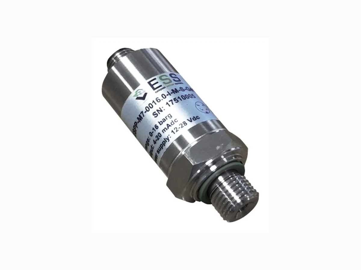
ESPP-MIT1 ES
Document overview
- Manufacturer or author: Provided By www.digicamel.com(FREE DATASHEET DOWNLOAD SITE)
- PDF pages: 8
Technical content
v1.5 Datasheet ESPP-MIT1
- Excellent performance at very low cost
- Micro-fused technology
- Pressure Type: Gauge
- Calibrated & temperature compensated output
- Full Scale (FS) Pressure Range: from 7 to 1000 bar
- Analog Output: 4-20mA, 05.-4.5V, 1-5V, 0-5V
- Compensation temperature: -10oC ... 80oC
- Operating temperature: -40oC … 125oC
- Total error: ≤ ±1%FS
- Integrated stainless steel construction, full sealed (IP65)
- Compact structure
- Wide range of process interfaces Typical Applications
- Central air conditioning control systems
- Engineering machinery
- Energy & water treatment systems
- Hydraulic & pneumatic systems
- Industrial process control & automatic detection systems
- Pumps & compressors
- Refrigeration systems Product Summary ES Systems has developed a series of pressure sensor transmitters featuring very good accuracy at low cost. Each module is based on all welded hermetically sealed structure in a single stainless -steel piece. The ESPP -MIT1 is a medium isolated pressure sensor suitable for gas or fluid pressure measurements in harsh environments. The output is fully calibrated and temperature compensated based on the internal temperature sensor and the factory calibration coefficients which are stored in the embedded memory. Thus, the transducer is ready to be installed directly to the end user system without further processing. ESPP-MIT1 comes with a variety of electrical interfaces output signal types and process interfaces. It is one of the most cost -effective solutions especially when high volumes are required. Strain Gauge Pressure Transmitter A ll data sheet.com
- Operating Specifications Characteristic Unit Min. Typ. Max. Pressure Type Gauge - Pressure Range Up to 1000 bar Power Supply (Vsupply) +8 +28 V Current Consumption 4 mA Total Error Band1 - ±1.0 %F.S.2 Operating temperature range3 -40[-40] - +125[257] oC[oF] Compensated temperature range4 -10[14] - 80[176] oC[oF] Storage temperature range -40[-40] - +125[257] oC[oF] Output Calibrated Pressure - Output Interface (Out) 4-20mA, 0.5-4.5V, 1-5V, 0-5V5 - Current Output Load Resistance ≤ (Vsupply – 8) / 0.02 Ohm Voltage Output Load Resistance 10K Ohm Response Time6 50 msec Warm-up Time7 100 msec Media Compatibility Gases, Liquids - Material Stainless Steel 17-4PH - IP rating IP65 - Certifications CE, RoHS, REACH - O-ring sealing Viton - 1 Total Error Band: The maximum deviation from ideal transfer function over the entire compensated temperature and pressure range. Includes all errors due to offset, full scale span, pressure non -linearity, pressure hysteresis, repeatability, thermal effect on offset, thermal effect on span and thermal hysteresis 2 % of the full scale pressure range 3 Operating temperature range: The temperature range over which the sensor will produce an output proportional to pressure 4 Compensated temperature range: The temperature range over which the sensor will produce an output proportional to pressure within the specified performance limits. 5 For 0-5V output, Vsupply is +11V to +28V. 6 Response Time: The time it takes for the electrical output to go from 10%FS signal to 90%FS signal and vice versa. 7 Warm-up Time: Time to the first valid pressure measurement after power is applied. A ll data sheet.com
- Pressure Specifications (bar) Option Pressure Range Over Pressure1 Burst Pressure2 Pmin Pmax 0007BG 0 7 14 35 0010BG 0 10 20 50 0016BG 0 16 32 80 0030BG 0 30 60 150 0050BG 0 50 100 250 0100BG 0 100 200 500 0150BG 0 150 300 750 0250BG 0 250 500 1250 0300BG 0 300 600 1500 0350BG 0 350 700 1750 0400BG 0 400 800 2000 0600BG 0 600 1200 2000 0800BG 0 800 1500 2000 1000BG 0 1000 1500 2000 1 Overpressure: The maximum pressure which may safely be applied to the product for it to remain in specification once pressure is returned to the operating pressure range. Exposure to higher pressures may cause permanent damage to the product. Unless otherwise specified this applies to all available pressure ports at any temperature with the operating temperature range 2 Burst pressure: The maximum pressure that may be applied to the specified port of the product without causing escape of pressure media. Product should not be expected to function after exposure to any pressure beyond the burst pressure 2 wire (current) 3 wire (voltage) 2. Wiring Diagrams A ll data sheet.com
- Output Type 5. Electrical Connector & Mechanical Dimensions 01. M12 02. ISO4400 03. Cable 04. Packard In order to calculate the total height of each of the options above, the height of the mechanical dimensions must be added to the height of the process interface (see section 5). Current Voltage Current Voltage Current Voltage Current Voltage Vsupply1 1 1 1 1 Black Black 1 1 Gnd1 - 2 - 2 - Yellow - 2 Out 3 3 2 3 Red Red 3 3 Chassis - - 3 4 - - - -
1 Note that Vsupply & Gnd are reverse polarity protected
1 Note all dimensions are in millimeters (mm)
A ll data sheet.com
- Process Interface (dimensions in mm) 01. 1/2” NPT male 1 02. 1/4” NPT male 1 03. G1/2” male 2 04. G1/4” male 2 05. 1/8” NPT male 1 06. G1/8” male 2 07. G3/8” male 2 08. 1/4” NPT female 1 09. 1/8” NPT female 1 A ll data sheet.com
- Process Interface (dimensions in mm) 10. G1/4” Female 3 11. R1/4” male 4 12. 7/16-20 UNF-2B 5 Note that for pressure ranges greater than 200bar, only options 02, 03, 04, 07 and 15 are available. 1 According to ANSI/ASME B1.20.1
2 According to ISO 1179-2 (DIN 3852-E)
3 According to EN837
4 According to ISO7
5 According to SAE J513
6 According to GB/T193
7 According to ISO 9974-2 (DIN 3852-E)
A ll data sheet.com
- Ordering Information ESPP-MIT1-NNNNNN-NN-NN-NN Pressure Range Full Scale 0007BG 7 bar 0010BG 10 bar 0016BG 16 bar 0030BG 30 bar 0050BG 50 bar 0100BG 100 bar 0150BG 150 bar 0250BG 250 bar 0300BG 300 bar 0350BG 350 bar 0400BG 400 bar 0600BG 600 bar 0800BG 800 bar 1000BG 1000 bar Process Interface 01 1/2” NPT male 02 1/4” NPT male
03 G1/2” male
04 G1/4” male
05 1/8” NPT male
06 G1/8” male
07 G3/8” male
08 1/4” NPT female 09 1/8” NPT female
10 G1/4” female
11 R1/4” male
13 M12x1 male
14 M14x1.5 male 15 M20x1.5 male Connector
01 M12
02 ISO4400
03 Cable (0.5m)
04 Packard
02 0.5-4.5V 03 1-5V 04 0-5V Output Type Equation Option 4-20mA 01. 0.5 - 4.5V 1- 5V 0- 5V 7. Pressure Conversion Table A ll data sheet.com
DO NOT USE these products as safety or emergency stop devices, or in any other application where failure of the product could result in personal injury. Failure to comply with these instructions could result in death or serious injury. WARRANTY ES Systems warrants this Product to be free of defects in materials and workmanship for a period of one (1) year from the date of purchase. Upon examination by ES Systems, if the unit is found to be defective it will be repaired or replaced at no charge. ES Systems' WARRANTY does not apply to defects resulting from any action of the purchaser, including but not limited to mishandling, improper interfacing, operation outside of design limits, improper repair, or unauthorized modification. This WARRANTY is VOID if the unit shows evidence of having been tampered with or shows evidence of being damaged as a result of excessive corrosion; or current, heat, moisture or vibration; improper specification; misapplication; misuse or other operating conditions outside of ES Systems' control. Components which wear are not warranted. ES Systems neither assumes responsibility for any omissions or errors nor assumes liability for any damages that result from the use of its Product in accordance with information provided by ES Systems, either verbal or written. ES Systems warrants only that the parts manufactured by it will be as specified and free of defects. ES SYSTEMS MAKES NO OTHER WARRANTIES OR REPRESENTATIONS OF ANY KIND WHATSOEVER, EXPRESSED OR IMPLIED, EXCEPT THAT OF TITLE, AND ALL IMPLIED WARRANTIES INCLUDING ANY WARRANTY OF MERCHANTABILITY AND FITNESS FOR A PARTICULAR PURPOSE ARE HEREBY DISCLAIMED. No representative of ES Systems is authorized to extend this Warranty or to change it in any manner whatsoever. No warranty applies to any party other than the original Customer. The remedies of the Customer set forth herein are exclusive and the total liability of ES Systems with respect to this order, whether based on contract, warranty, negligence, indemnification, strict liability or otherwise, shall not exceed the purchase price of the component upon which liability is based. In no event shall ES Systems be liable for consequential, incidental or special damages. Specifications may change without notice. The information supplied is believed to be accurate and reliable as of this issue; however, ES Systems assumes no responsibility for its use. ES Systems S.A. Head Office: 7, Stratigi St., GR-154 51 Neo Psychico, Greece Tel: (+30) 210 672 8610, Fax (+30) 210 672 8624 Factory: 57, I.Metaxa str., GR-194 41 Koropi, Greece Tel: (+30) 216 2000 500, Fax (+30) 216 2000 555 Important Notes A ll data sheet.com