
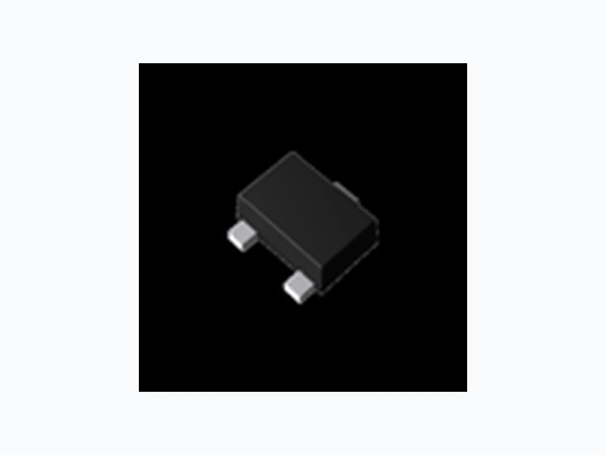
DTA013Z ROHM
Document overview
- Manufacturer or author: Provided By www.digicamel.com(FREE DATASHEET DOWNLOAD SITE)
- PDF pages: 8
Technical content
PNP -100mA -50V Digital Transistors (Bias Resistor Built-in Transistors) Datasheet llOutline Parameter Value VMT3 EMT3F VCC -50V IC(MAX.) -100mA R1 1.0kΩ DTA013ZM DTA013ZEB R2 10kΩ (SC-105AA) (SC-89) UMT3F llFeatures 1) Built-In Biasing Resistors, R1 = 1kΩ, R2 = 10kΩ 2) Built-in bias resistors enable the configuration of an inverter circuit without connecting external input resistors (see inner circuit) . 3) The bias resistors consist of thin-film resistors with complete isolation to allow negative biasing of the input. They also have the advantage of completely eliminating parasitic effects. 4) Only the on/off conditions need to be set for operation, making the circuit design easy . 5) Complementary NPN Types: DTC013Z series 6) Lead Free/RoHS Compliant. DTA013ZUB (SC-85) llInner circuit llApplication Switching circuit, Inverter circuit, Interface circuit, Driver circuit llPackaging specifications Part No. Package Package size Taping code Reel size (mm) Tape width (mm) Basic ordering unit.(pcs) Marking DTA013ZM VMT3 1212 T2L 180 8 8000 57 DTA013ZEB EMT3F 1616 TL 180 8 3000 57 DTA013ZUB UMT3F 2021 TL 180 8 3000 57 www.rohm.com © 2013 ROHM Co., Ltd. All rights reserved. 1/7 20130828 - Rev.002
llAbsolute maximum ratings (Ta = 25°C) Parameter Symbol Values Unit Supply voltage VCC -50 V Input voltage VIN -10 to 5 V Output current IO -100 mA Collector current IC(M A X )*1 -100 mA Power dissipation DTA013ZM PD*2 150 mW DTA013ZEB 150 DTA013ZUB 200 Junction temperature Tj 150 ℃ Range of storage temperature Tstg -55 to +150 ℃ llElectrical characteristics (Ta = 25°C) Parameter Symbol Conditions Values Unit Min. Typ. Max. Input voltage VI(off) VCC = -5V, IO = -100μA - - -0.4 V VI(on) VO = -0.3V, IO = -5mA -1.0 - - Output voltage VO(on) IO / II = -5mA / -0.5mA - -0.07 -0.15 V Input current II VI = -5V - - -7.2 mA Output current IO(off) VCC = -50V, VI = 0V - - -500 nA DC current gain GI VO = -10V, IO = -5mA 30 - - - Input resistance R1 - 0.7 1.0 1.3 kΩ Resistance ratio R2/R1 - 8 10 12 - Transition frequency fT*1 VCE = -10V, IE = 5mA, f = 100MHz - 250 - MHz *1 Characteristics of built-in transistor *2 Each terminal mounted on a reference footprint www.rohm.com © 2013 ROHM Co., Ltd. All rights reserved. 2/7 20130828 - Rev.002
llElectrical characteristic curves (Ta =25°C) Fig.1 Input voltage vs. output current (ON characteristics) Fig.2 Output current vs. input voltage (OFF characteristics) Fig.3 Output current vs. output voltage Fig.4 DC current gain vs. output current www.rohm.com © 2013 ROHM Co., Ltd. All rights reserved. 3/7 20130828 - Rev.002
llElectrical characteristic curves (Ta =25°C) Fig.5 Output voltage vs. output current www.rohm.com © 2013 ROHM Co., Ltd. All rights reserved. 4/7 20130828 - Rev.002
www.rohm.com © 2013 ROHM Co., Ltd. All rights reserved. 5/7 20130828 - Rev.002
www.rohm.com © 2013 ROHM Co., Ltd. All rights reserved. 6/7 20130828 - Rev.002
www.rohm.com © 2013 ROHM Co., Ltd. All rights reserved. 7/7 20130828 - Rev.002