
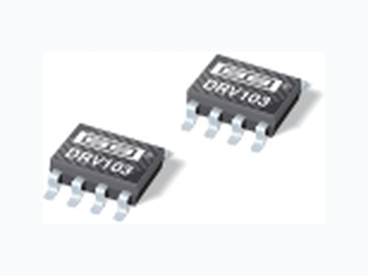
DRV103 TI
Document overview
- Manufacturer or author: Provided By www.digicamel.com(FREE DATASHEET DOWNLOAD SITE)
- PDF pages: 17
Technical content
PRODUCTION DATA information is current as of publication date. Products conform to specifications per the terms of Texas Instruments standard warranty. Production processing does not necessarily include testing of all parameters. PWM LOW-SIDE DRIVER (1.5A and 3A) for Solenoids, Coils, Valves, Heaters, and Lamps
FEATURES
G HIGH OUTPUT DRIVE: 1.5A and 3A Versions G WIDE SUPPLY RANGE: +8V to +32V G COMPLETE FUNCTION Digitally Controlled Input PWM Output Adjustable Internal Oscillator: 500Hz to 100kHz Adjustable Delay and Duty Cycle G FULLY PROTECTED Thermal and Current Limit Shutdown with Status OK Indicator Flag G PACKAGES: SO-8 and PowerPAD™ SO-8
APPLICATIONS
G ELECTROMECHANICAL DRIVER: Solenoids, Valves, Positioners, Actuators, Relays, Power Contactor Coils, Heaters, Lamps G HYDRAULIC AND PNEUMATICS SYSTEMS G PART HANDLERS AND SORTERS G CHEMICAL PROCESSING G ENVIRONMENTAL MONITORING AND HVAC G THERMOELECTRIC COOLERS G DC MOTOR SPEED CONTROLS G MEDICAL AND SCIENTIFIC ANALYZERS G FUEL INJECTOR DRIVERS
DESCRIPTION
The DRV103 is a low-side DMOS power switch employing a pulse-width modulated (PWM) output. Its rugged design is optimized for driving electromechanical devices such as valves, solenoids, relays, actuators, motors, and positioners. The DRV103 is also ideal for driving thermal devices such as heaters, coolers, and lamps. PWM operation conserves power and reduces heat rise, resulting in higher reliability. In addition, adjustable PWM allows fine control of the power delivered to the load. DC-to-PWM output delay time and oscillator frequency are also externally adjustable. The DRV103 can be set to provide a strong initial closure, automatically switching to a “soft” hold mode for power savings. A resistor, analog voltage, or Digital-to-Analog (D/A) converter can control the duty cycle. An output OK flag indicates when thermal shutdown or over current occurs. Two packages provide a choice of output current: 1.5A (SO-8) or 3A (PowerPAD™ SO-8 with exposed metal heat sink). The DRV103 is specified for –40°C to +85°C. Delay Adj C D R PWM Input On Off Thermal Shutdown Over Current Status OK Flag Load +V S OscillatorVREF PWM GND OUT Flyback DiodeDMOS DMOS ESD Osc Freq Adj Duty Cycle Adj R FREQ Delay DRV103 DRV103 SBVS029A – JUNE 2001 www.ti.com Copyright © 2001, Texas Instruments Incorporated Please be aware that an important notice concerning availability, standard warranty, and use in critical applications of Texas Instruments semiconductor products and disclaimers thereto appears at the end of this data sheet. PowerPAD is a trademark of Texas Instruments. DRV103 DRV103
DRAWING TEMPERATURE PACKAGE ORDERING TRANSPORT PRODUCT PACKAGE NUMBER RANGE MARKING NUMBER (1) MEDIA DRV103U SO-8 182 –40 °C to +85°C DRV103U DRV103U Rails " " " " " DRV103U/2K5 Tape and Reel DRV103H PowerPAD™ SO-8 DDA –40 °C to +85°C DRV103H DRV103H Rails " " " " " DRV103H/2K5 Tape and Reel NOTES: (1) Models with a slash (/) are available only in Tape and Reel in the quantities indicated (e.g., /2K5 indicates 2500 devices per reel). Ordering 2500 pieces of “DRV103U/2K5” will get a single 2500-piece Tape and Reel. NOTES: (1) Stresses above these ratings may cause permanent damage. Exposure to absolute maximum conditions for extended periods may de- grade device reliability. (2) See Bypassing section for discussion about operating near maximum supply voltage. (3) Higher voltage may be applied if current is limited to 2mA. (4) The Status OK Flag will internally current limit at about 10mA. ABSOLUTE MAXIMUM RATINGS (1) ELECTROSTATIC DISCHARGE SENSITIVITY This integrated circuit can be damaged by ESD. Texas Instru- ments recommends that all integrated circuits be handled with appropriate precautions. Failure to observe proper handling and installation procedures can cause damage. ESD damage can range from subtle performance degradation to complete device failure. Precision integrated circuits may be more susceptible to damage because very small parametric changes could cause the device not to meet its published specifications. PACKAGE/ORDERING INFORMATION
ELECTRICAL CHARACTERISTICS
At TC = +25°C, VS = +24V, Load = 100Ω , and 4.99kΩ “OK Flag” pullup to +5V, Delay Adj Capacitor = 100pF to Ground, Freq Adj Resistor = 205kΩ to Ground, Duty Cycle Adj Resistor = 137kΩ to Ground, unless otherwise noted. DRV103U, H PARAMETER CONDITIONS MIN TYP MAX UNITS OUTPUT Output Current (1) SO-8 Package (U) 1.5 A PowerPAD™ SO-8 Package (H) 3 A Output Saturation Voltage, Source I O = 1A +0.4 +0.6 V Current Limit(2), (10) 3 3.5 4.2 A Leakage Current DMOS Output Off, V O = +32V ±1 ±10 µA DIGITAL CONTROL INPUT (3) VCTR Low (output disabled) 0 +1.2 V VCTR High (output enabled) +2.2 +5.5 V ICTR Low (output disabled) V CTR = 0V 0.01 1 µA ICTR High (output enabled) V CTR = +5.5V 120 150 µA Propagation Delay On-to-Off and Off-to-On 1 µs DELAY TO PWM (4) DC to PWM Mode Delay Equation(5) See Note (6) s Delay Time C D = 0.1µF 90 110 140 ms Minimum Delay Time(7) C D = 0 18 µs DUTY CYCLE ADJUST Duty Cycle Range 10 to 90 % Duty Cycle Accuracy 50% Duty Cycle, 25kHz ±2% vs Supply Voltage 50% Duty Cycle, V S = VO = +8V to +32V ±2% Nonlinearity(8) 10% to 90% Duty Cycle 1 % FSR DYNAMIC RESPONSE Output Voltage Rise Time V O = 10% to 90% of VS 0.2 2 µs Output Voltage Fall Time V O = 90% to 10% of VS 0.2 2 µs Oscillator Frequency Range External Adjust 0.5 to 100 kHz Oscillator Frequency R OSC = 205kΩ 20 25 30 kHz OK FLAG Normal Operation 20k Ω Pull-Up to +5V +4.5 5.0 V Fault(90) Sinking 1mA +0.22 +0.4 V Sink Current V OKFLAG = 0.4V 2 mA Over-Current Flag: Set 5 µs THERMAL SHUTDOWN Junction Temperature Shutdown +160 °C Reset from Shutdown +140 °C POWER SUPPLY Specified Operating Voltage +24 V Operating Voltage Range +8 +32 V Quiescent Current I O = 0 0.4 0.8 mA TEMPERATURE RANGE Specified Range –40 +85 °C Operating Range –55 +125 °C Storage Range –65 +150 °C Thermal Resistance, θJA SO-8 (U) 1in 2 0.5oz. Copper on PCB 150 °C/W PowerPAD™ SO-8 (H) (10) 1in2 0.5oz. Copper on PCB 68 °C/W NOTES: (1) Output current is limited by internal current limit and by DRV103 power dissipation. (2) Output current resets to zero when current limit is reached. (3) Logic High enables output (normal operation). (4) Constant DC output to PWM (Pulse-Width Modulated) time. (5) Maximum delay is determined by an external capacitor. Pulling the Delay Adjust Pin LOW corresponds to an infinite (continuous) delay. (6) Delay to PWM ≈ C D • 10 6 (C D in F • 1.1). (7) Connecting the Delay Adjust Pin to +5V reduces delay time to less than 1µs. (8) VIN at pin 3 to percent of duty cycle at pin 6. (9) OK Flag LOW indicates fault from over-temperature or over-current conditions. (10) PowerPAD™ SO-8 (H) package has highest continuous current (2A) because the chip operates at a lower junction temperature when underside metal tab is connected to a heat sink or heat spreader. θJA = 68°C/W measured on DRV103 demo board; θJA = 58°C/W measured on JEDEC standard test board. H package θJC = 16.7°C/W.
PIN # NAME DESCRIPTION Pin 1 Duty Cycle Adjust Internally, this pin connects to the input of a comparator and a (2.75 x IREF ) current source from VS. The voltage at this node linearly sets the duty cycle. Duty cycle can be programmed with a resistor, analog voltage, or the voltage output of a D/A converter. The active voltage range is from 1.3V to 3.9V to facilitate the use of single-supply control electronics. At 3.56V, output duty cycle is near 90%. At 1.5V, output duty cycle is near 10%. Pin 2 Delay Adjust This pin sets the duration of the initial 100% duty cycle before the output goes into PWM mode. Leaving this pin floating results in a delay of approximately 18µs, which is internally limited by parasitic capacitance. Minimum delay may be reduced to less than 1µs by tying the pin to 5V. This pin connects internally to a 3µA current source from VS and to a 2.6V threshold comparator. When the pin voltage is below 2.6V, the output device is 100% ON. The PWM oscillator is not synchronized to the Input (pin 1), so the duration of the first pulse may be any portion of the programmed duty cycle. Pin 3 Oscillator PWM frequency is adjustable. A resistor to ground sets the current IREF and the internal PWM oscillator frequency. A range of 500Hz Frequency Adjust to 100kHz can be achieved with practical resistor values. Although oscillator frequency operation below 500Hz is possible, resistors higher than 10M will be required. The pin then becomes a very high impedance node and is, therefore, sensitive to noise pickup and PCB leakage currents. Pin 4 GND This pin must be connected to system ground for the DRV103 to function. It carries the 0.4mA quiescent current plus the full load current when the power DMOS transistor is switched on. Pin 5 OUT The output is the drain of a power DMOS transistor with its source connected to ground. Its low on-resistance (0.5Ω typ) assures low power dissipation in the DRV103. Gate drive to the power device is controlled to provide a slew-rate limited rise and fall time. This reduces radiated RFI/EMI noise. A flyback diode is needed with inductive loads to conduct the load current during the off cycle. The external diode should be selected for low forward voltage and low storage time. The internal clamp diode (an ESD protection diode) provides some degree of back-EMF protection but it should not be used as a flyback diode. Pin 6 +V S This is the power supply pin. Operating range is +8V to +32V. +VS must be ≥ the supply voltage to the load. Pin 7 Status OK Flag Normally HIGH (active LOW), a Flag LOW signals either an over-temperature or over-current fault. The over-current flag (Status OK) is LOW only when the output is ON (constant DC output or the “ON” portion of PWM mode). A thermal fault (thermal shutdown) occurs when the die surface reaches approximately 160°C and latches until the die cools to 140°C. This output requires a pull- up resistor and it can typically sink 2mA, sufficient to drive a low-current LED. Sink current is internally limited at 10mA typical. Pin 8 Input The input is compatible with standard TTL levels. The device output becomes enabled when the input voltage is driven above the typical switching threshold, 1.7V. Below this level, the output is disabled. Input current is typically 10nA when driven HIGH and 10nA with the input LOW. The input should not be directly connected to the power supply (V S) or damage will occur. PIN DESCRIPTIONS LOGIC BLOCK DIAGRAM PIN CONFIGURATION Top View Duty Cycle Adj Delay Adj Osc Freq Adj GND Input Status OK Flag S OUT Delay Adj C D R PWM Input On Off Thermal Shutdown Over Current Status OK Flag Load +V S Oscillator1.3V VREF PWM GND OUT Flyback DiodeDMOS DMOS ESD Osc Freq Adj Duty Cycle Adj 2.75 • IREF R FREQ Delay DRV103 IREF SO
At TC = +25°C and VS = +24V, unless otherwise noted. VOUT & IOUT WAVEFORMS SOLENOID LOAD On On Off IAVG PWM Mode Delay Pull-In IOUT (A) Time (ms) 1000 +VS +VS R L VOUT & IOUT WAVEFORMS RESISTIVE LOAD On Off IAVG PWM Mode Delay IOUT (A) Time (ms) 1000 +VS +VS R L CURRENT LIMIT SHUTDOWN WAVEFORMS On OK OK OK OK Off Off FPWM = 25kHz DC = 50% Delay = 150µs Reset Period = 1/F PWM VIN (V) VOUT (V) Time (µs) 1000 VIN VOUT IO = 0A IO = 3.5A OK Status OK Flag Reset Period 5.0 4.5 4.0 3.5 3.0 2.5 2.0 1.5 1.0 0.5 –10–60 IQ (mA) 40 90 140 QUIESCENT CURRENT vs JUNCTION TEMPERATURE Temperature (°C) 32V 8V to 24V 40V (Absolute Maximum) 3.8 3.7 3.6 3.5 3.4 3.3 –10–60 Current (A) 40 90 140 CURRENT LIMIT vs JUNCTION TEMPERATURE Temperature (°C) 150 145 140 135 130 125 120 115 110 105 100 –10–60 Delay (ms) 40 90 140 DELAY vs JUNCTION TEMPERATURE Temperature (°C) C D = 0.1µF +VS = 8V +VS = 30V +VS = 24V +VS = 40V (Absolute Maximum)
TYPICAL CHARACTERISTICS (Cont.) At TC = +25°C and VS = +24V, unless otherwise noted. –10–60 Min Delay (µs) 40 90 140 MINIMUM DELAY vs JUNCTION TEMPERATURE Temperature (°C) C D = 0pF 25.5 25.3 25.1 24.9 24.7 –10–60 Frequency (kHz) 40 90 140 OSCILLATOR FREQUENCY vs JUNCTION TEMPERATURE Temperature (°C) 50.8 50.6 50.4 50.2 50.0 49.8 49.6 49.4 49.2 –10–60 Duty Cycle (%) 40 90 140 DUTY CYCLE vs JUNCTION TEMPERATURE Temperature (°C) R PWM = 137kΩ 1.6 1.4 1.2 1.0 0.8 0.6 0.4 0.2 –10–60 VSAT (V) 40 90 140 VSAT vs JUNCTION TEMPERATURE Temperature (°C) IO = 3A IO = 1.5A IO = 0.1AIO = 0.5A 1.287 1.286 1.285 1.284 1.283 1.282 1.281 1.280 1.279 1.278 1.277 1.276 –10–60 VFREQ (V) 40 90 140 VFREQ vs JUNCTION TEMPERATURE Temperature (°C) 300 250 200 150 100 –50 4.54 Input Current (µA) 5 5.5 6 INPUT CURRENT vs INPUT VOLTAGE Input Voltage (V)
The internal protection circuitry of the DRV103 was designed to protect against overload conditions. It was not intended to replace proper heat sinking. Continuously running the DRV103 into thermal shutdown will degrade reliability. HEAT SINKING Most applications will not require a heat sink to assure that the maximum operating junction temperature (125°C) is not exceeded. However, junction temperature should be kept as low as possible for increased reliability. Junction tempera- ture can be determined according to the equation: T J = TA + PD θJA (1) where, θJA = θJC + θCH + θHA (2) TJ = Junction Temperature (°C) TA = Ambient Temperature (°C) PD = Power Dissipated (W) θJC = Junction-to-Case Thermal Resistance (°C/W) θCH = Case-to-Heat Sink Thermal Resistance (°C/W) θHA = Heat Sink-to-Ambient Thermal Resistance (°C/W) θJA = Junction-to-Air Thermal Resistance (°C/W) Using a heat sink significantly increases the maximum allowable power dissipation at a given ambient temperature. The answer to the question of selecting a heat sink lies in determining the power dissipated by the DRV103. For DC output into a purely resistive load, power dissipation is simply the load current times the voltage developed across the conducting output transistor times the duty cycle. Other loads are not as simple. For further insight on calculating power dissipation, refer to Application Bulletin SBFA002 at www.ti.com. Once power dissipation for an application is known, the proper heat sink can be selected. Heat Sink Selection Example A PowerPAD™ SO-8 (H) package is dissipating 2W. The maximum expected ambient temperature is 35°C. Find the proper heat sink to keep the junction temperature below 125°C. Combining Equations 1 and 2 gives: T J = TA + PD (θJC + θCH + θHA )( 3 ) TJ, TA , and PD are given. θJC is provided in the specification table, 16.7°C/W. θCH depends on heat sink size, area, and material used. A semiconductor’s package type and mount- ing can also affect θCH . A typical θCH for a soldered-in-place PowerPAD™ SO-8 (H) package is 2 °C/W. Now we can solve for θHA : θθ θ θ θ HA JA D JC CH HA HA TT P CC W CW CW CW =+ () = °° °+ °() – – – –. / / 125 35 2 16 7 2 26 3 (4) To maintain junction temperature below 125°C, the heat sink selected must have a θHA less than 26.3°C/W. In other words, the heat sink temperature rise above ambient must be less than 52.6°C (26.3°C/W • 2W). Another variable to consider is natural convection versus forced convection air flow. Forced-air cooling by a small fan can lower θCA (θCH + θHA ) dramatically. As mentioned earlier, once a heat sink has been selected, the complete design should be tested under worst-case load and signal conditions to ensure proper thermal protection. RFI/ EMI Any switching system can generate noise and interference by radiation or conduction. The DRV103 is designed with controlled slew rate current switching to reduce these ef- fects. By slowing the rise and fall times of the output to 0.3µs, much lower switching noise is generated. Radiation from the DRV103-to-load wiring (the “antenna” effect) can be minimized by using “twisted pair” cable or by shielding. Good PCB ground planes are recommended for low noise and good heat dissipation. Refer to Bypassing section for notes on placement of the flyback diode. BYPASSING A 1µF tantalum bypass capacitor is adequate for uniform duty cycle control when switching loads of less than 0.5 amps. Larger bypass capacitors are required when switching high current loads. A 22µF tantalum capacitor is recom- mended for heavy-duty (3A) applications. It may also be desirable to run the DRV103 and the load on separate power supplies at high load currents. Near the absolute maximum supply voltage of 40V, bypassing is especially critical. In the event of a current overload, the DRV103 current limit responds in microseconds, dropping the load current to zero. With inadequate bypass, energy stored in the supply line inductance can lift the supply sufficiently to exceed voltage breakdown with catastrophic results. Place the flyback diode at the DRV103 end when driving long (inductive) cables to a remotely located load. This minimizes RFI / EMI and helps protect the output DMOS transistor from breakdown caused by dI/dt transients. Fast rectifier diodes such as epitaxial silicon or Schottky types are recommended as flyback diodes.
Texas Instruments Incorporated and its subsidiaries (TI) reserve the right to make corrections, modifications, enhancements, improvements, and other changes to its products and services at any time and to discontinue any product or service without notice. Customers should obtain the latest relevant information before placing orders and should verify that such information is current and complete. All products are sold subject to TI’s terms and conditions of sale supplied at the time of order acknowledgment. TI warrants performance of its hardware products to the specifications applicable at the time of sale in accordance with TI’s standard warranty. Testing and other quality control techniques are used to the extent TI deems necessary to support this warranty. Except where mandated by government requirements, testing of all parameters of each product is not necessarily performed. TI assumes no liability for applications assistance or customer product design. Customers are responsible for their products and applications using TI components. To minimize the risks associated with customer products and applications, customers should provide adequate design and operating safeguards. TI does not warrant or represent that any license, either express or implied, is granted under any TI patent right, copyright, mask work right, or other TI intellectual property right relating to any combination, machine, or process in which TI products or services are used. Information published by TI regarding third-party products or services does not constitute a license from TI to use such products or services or a warranty or endorsement thereof. Use of such information may require a license from a third party under the patents or other intellectual property of the third party, or a license from TI under the patents or other intellectual property of TI. Reproduction of information in TI data books or data sheets is permissible only if reproduction is without alteration and is accompanied by all associated warranties, conditions, limitations, and notices. Reproduction of this information with alteration is an unfair and deceptive business practice. TI is not responsible or liable for such altered documentation. Resale of TI products or services with statements different from or beyond the parameters stated by TI for that product or service voids all express and any implied warranties for the associated TI product or service and is an unfair and deceptive business practice. TI is not responsible or liable for any such statements. Following are URLs where you can obtain information on other Texas Instruments products and application solutions: Products Applications Amplifiers amplifier.ti.com Audio www.ti.com/audio Data Converters dataconverter.ti.com Automotive www.ti.com/automotive DSP dsp.ti.com Broadband www.ti.com/broadband Interface interface.ti.com Digital Control www.ti.com/digitalcontrol Logic logic.ti.com Military www.ti.com/military Power Mgmt power.ti.com Optical Networking www.ti.com/opticalnetwork Microcontrollers microcontroller.ti.com Security www.ti.com/security Telephony www.ti.com/telephony Video & Imaging www.ti.com/video Wireless www.ti.com/wireless Mailing Address: Texas Instruments Post Office Box 655303 Dallas, Texas 75265 Copyright 2004, Texas Instruments Incorporated