
C8051F041 ETC
Document overview
- Manufacturer or author: Provided By www.digicamel.com(FREE DATASHEET DOWNLOAD SITE)
- PDF pages: 2
Technical content
C8051F041 CAN2.0B 64KB ISP FLASH MCU PRELIMINARY UART1 SMBus SPI Bus PCA Timers 0,1,2,3,4 VDD VDD VDD DGND DGND DGND /RST XTAL1 XTAL2 Internal Oscillator P2.0/CPx P2.7/CPx P0.0 P0.7 DAC1 DAC1 (12-Bit) VREF DAC0 (12-Bit) AIN0.0 AIN0.1 AIN0.2 AIN0.3 DAC0 VREF UART0 8:1 MONEN WDT VREFA P7 Latch P5 Latch P6 Latch DRV DRV DRV Addr [15:8] Addr [7:0] Ctrl Latch Data Latch A M U X 8:2 HVAIN+ HVAIN- HVREF HVCAP HVAMP TEMP SENSOR Drv Drv Drv Drv Port 0,1,2,3 Latches CAN 2.0B CRX0 CTX0 C o r e Reset A M U X ADC 100ksps (12-Bit) External Data Memory Bus 32x136 CANRAM 256 byte RAM 4K byte XRAM P3.0/AIN0.6 P3.7/AIN0.7 P1.0/AIN1.0 P1.7/AIN1.7 64K byte FLASH System Clock External Oscillator Circuit VDD Monitor C R O S S B A R Data [7:0] Address [15:0] Bus Control Digital Power Port 4 <from crossbar> A M U X ADC 500KS/s (8-Bit) P2.1 P2.0+ -CP0 P2.3 P2.2+ -CP1 P2.5 P2.4+ -CP2 SFR Bus DRV Debug HW Boundary ScanJTAG Logic TCK TMS TDI TDO AGND AGND AV+ AV+ Analog Power Prog Gain Prog Gain VREFA ANALOG PERIPHERALS 12-bit ADC - ±1LSB INL; Guaranteed Monotonic - Programmable Throughput up to 100ksps - 12 External Inputs; Programmable as Single-Ended or Differential - Programmable Amplifier Gain: 16, 8, 4, 2, 1, 0.5 - Data Dependent Windowed Interrupt Generator - Built-in Temperature Sensor (± 3°C) High-Voltage Differential Amplifier - 60V Common Mode Input Range - Offset Adjust from –60V to +60V - 16 Gain Settings from 0.05 to 16 8-bit ADC - Programmable Throughput up to 500ksps - 8 External Inputs; Programmable as Single-Ended or Differential - Programmable Amplifier Gain: 4, 2, 1, 0.5 Two 12-bit DACs Three Comparators Internal Voltage Reference Precision VDD Monitor/Brown-out Detector ON-CHIP JTAG DEBUG & BOUNDRY SCAN - On-Chip Debug Circuitry Facilitates Full Speed, Non-Intrusive In- System Debug (No Emulator Required!) - Provides Breakpoints, Single Stepping, Watchpoints, Stack Monitor, Program Trace Memory - Inspect/Modify Memory and Registers - Superior Performance to Emulation Systems Using ICE-Chips, Target Pods, and Sockets - IEEE1149.1 Compliant Boundary Scan HIGH SPEED 8051 µµµµC CORE - Pipe-lined Instruction Architecture; Executes 70% of Instructions in 1 or 2 System Clocks - Up to 25MIPS Throughput with 25MHz System Clock - Expanded Interrupt Handler MEMORY - 4352 Bytes Internal Data RAM (256 + 4k) - 64k Bytes In-System Programmable FLASH Program Memory - External 64k Byte Data Memory Interface CAN Bus 2.0B - 32 Message Objects - “Mailbox” implementation only interrupts CPU when needed DIGITAL PERIPHERALS - 32 Port I/O; All are 5V tolerant - Hardware SMBusTM (I2CTM Compatible), SPITM, and Two UART Serial Ports Available Concurrently - Programmable 16-bit Counter Array with 6 Capture/Compare Modules - Five General Purpose 16-bit Counter/Timers - Dedicated Watch-Dog Timer; Bi-directional Reset CLOCK SOURCES - Internal Programmable 2% Oscillator: Up to 25MHz - External Oscillator: Crystal, RC, C, or Clock - Real-Time Clock Mode using Timer 3 or PCA - Typical Operating Current: 10mA @ 25MHz - Multiple Power Saving Sleep and Shutdown Modes 64-Pin TQFP; Temp Range –40°°°°C to +85°°°°C 8.6.2002
C8051F041 CAN2.0B 64KB ISP FLASH MCU PRELIMINARY SELECTED ELECTRICAL SPECIFICATIONS TA = -40°C to +85°C, VDD = 2.7V unless otherwise specified. PARAMETER CONDITIONS MIN TYP MAX UNITS GLOBAL CHARACTERISTICS Supply Voltage 2.7 3.6 V Supply Current (CPU active) Clock=25MHz Clock=1MHz Clock=32kHz; VDD Monitor Enabled 0.5 mA mA µA Supply Current (shutdown) Oscillator not running; VDD Monitor Disabled 0.1 µA Clock Frequency Range DC 25 MHz A/D CONVERTER Resolution 12 bits Integral Nonlinearity ± 1 LSB Differential Nonlinearity Guaranteed Monotonic ± 1 LSB Signal-to-Noise Plus Distortion 66 69 dB Throughput Rate 100 ksps Input Voltage Range 0 VREF V D/A CONVERTERS Resolution 12 LSB Differential Nonlinearity ± 1 LSB Output Settling Time 10 µs COMPARATORS Supply Current (each Comparator) 1.5 µA Response Time | CP+ – CP- | = 100mV 4 µs
PACKAGE INFORMATION
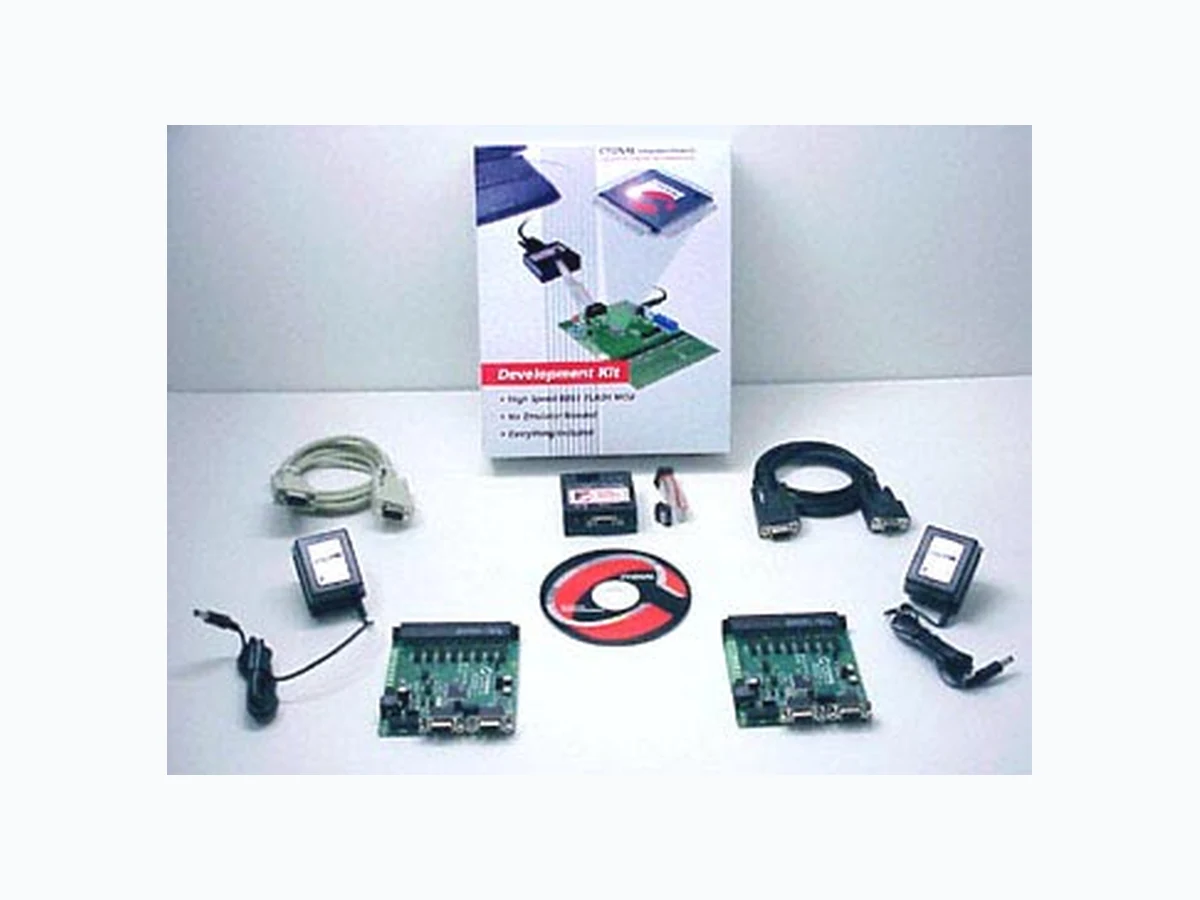
A b D e E 0.05 0.95 0.17 0.22 12.00 10.00 0.50 12.00 10.00 1.20 0.15 1.05 0.27 MIN (mm) NOM (mm) MAX (mm) E e A1b D PIN 1 DESIGNATOR A C8051F040DK DEVELOPMENT KIT SPI is a trademark of Motorola, Inc.; SMBus is a trademark of Intel Corp.; I2C is a trademark of Philips Semiconductors