
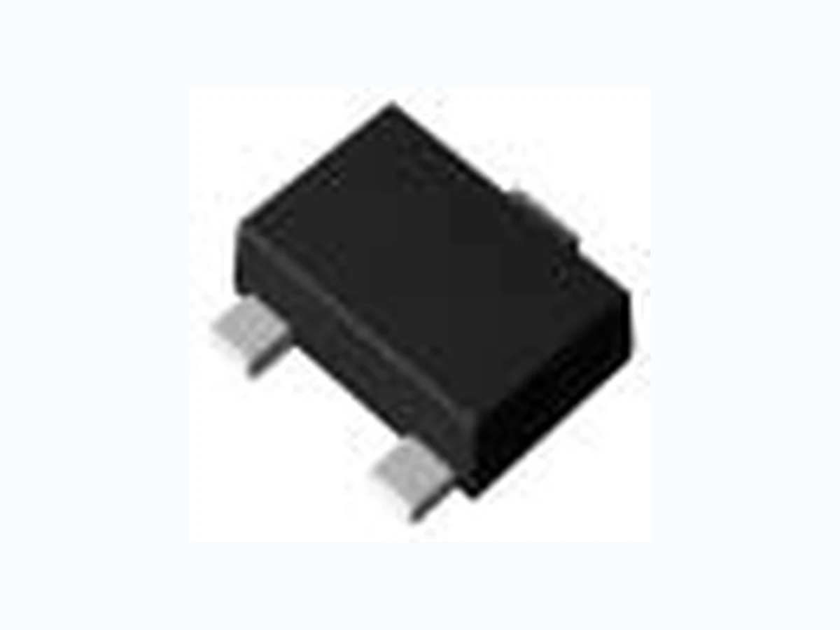
2SD2351T106W ROHM
Document overview
- Manufacturer or author: Provided By digicamel.com
- PDF pages: 11
Technical content
www.rohm.com © 2013 ROHM Co., Ltd. All rights reserved. 2SD2707 / 2SD2654 / 2SD2351 / 2SD2226K NPN 150mA 50V Muting Transistors lOutline lFeatures 1) High DC current gain. hFE =2700 (Max.) 2) High emitter-base voltage. VEBO is Min. 12V 3) Low VCE(sat) VCE(sat)=0.3V(Max.) (IC/IB=50mA/5mA) 4) Lead Free/RoHS Compliant. lInner circuit lApplications Muting circuit lPackaging specifications *1 x : hFE rank 2SD2707 V 2SD2654 8,000 BJx*1 EMT3 1616 TL 180 VMT3 1212 T2L 180 VW 180 8 3,000 UMT3 2021 T106 180 VMT3 EMT3 VCEO 50V Package size (mm) Taping code Reel size (mm) IC 150mA Parameter Value UMT3 SMT3 BJx*1 BJx*1 BJx*1 8 3,000 8 3,000 Tape width (mm)Package Basic ordering unit (pcs) MarkingPart No. hFE 2SD2351 VW 2SD2226K VW SMT3 2928 T146 2SD2707 (SC-105AA) Collector Base Emitter 2SD2654 SOT-416 (SC-75A) Collector Base Emitter 2SD2226K SOT-346 (SC-59) 2SD2351 SOT-323 (SC-70) Collector Base Emitter Collector Base Emitter Base Emitter Collector 1/10 2013.05 - Rev.B
www.rohm.com © 2013 ROHM Co., Ltd. All rights reserved. Data Sheet 2SD2707 / 2SD2654 / 2SD2351 / 2SD2226K lAbsolute maximum ratings (Ta = 25°C) Collector-base voltage Collector-emitter voltage Emitter-base voltage Junction temperature Range of storage temperature lElectrical characteristics (Ta = 25°C) *1 PW=10ms Single pulse. *2 Each terminal mounted on a reference footprint lhFE rank categories Tj 150 Rank V W hFE 820 to 1800 1200 to 2700 Max. 0.3 0.3 50 - - Conditions Min. Typ.Symbol VCE(sat) IC = 50mA, IB = 5mA - - Parameter Symbol Values Unit VCBO 60 V VCEO 50 V VEBO 12 V Power dissipation PD Collector current IC 150 2SD2226K,2SD2351 2SD2351,2SD2707 200 150 mW mW mA ICP *1 200 mA Tstg -55 to +150 °C - V Emitter-base breakdown voltage BVEBO IE = 10mA 12 - - V Collector-base breakdown voltage BVCBO IC = 10mA 60 - Unit Collector-emitter breakdown voltage BVCEO IC = 1mA V Parameter mA Emitter cut-off current IEBO VEB = 12V - - 0.3 mA Collector cut-off current ICBO VCB = 50V - - MHz Output capacitance Cob VCB = 5V, IE = 0mA f = 1MHz - 3.5 - pF Transition frequency fT VCE = 5V, IE = -10mA f=100MHZ - 250 V DC current gain hFE VCE = 5V, IC = 1mA 820 - 2700 - Collector-emitter saturation voltage 2/10 2013.05 - Rev.B
www.rohm.com © 2013 ROHM Co., Ltd. All rights reserved. Data Sheet 2SD2707 / 2SD2654 / 2SD2351 / 2SD2226K lElectrical characteristic curves(Ta = 25°C) Fig.1 Ground Emitter Propagation Characteristics COLLECTOR CURRENT : IC [mA] BASE TO EMITTER VOLTAGE : VBE [V] Fig.2 Typical Output Characteristics COLLECTOR CURRENT : IC [mA] COLECTOR TO EMITTE VOLTAGE : VCE [V] Fig.3 DC Current Gain vs. Collector Current(I) DC CURRENT GAIN : hFE COLLECTOR CURRENT : IC [mA] Fig.4 DC Current Gain vs. Collector Current(II) DC CURRENT GAIN : hFE COLLECTOR CURRENT : IC [mA] 3/10 2013.05 - Rev.B
www.rohm.com © 2013 ROHM Co., Ltd. All rights reserved. Data Sheet 2SD2707 / 2SD2654 / 2SD2351 / 2SD2226K lElectrical characteristic curves(Ta = 25°C) Fig.5 Collector-Emitter Saturation Voltage vs. Collector Current (I) COLLECTOR-EMITTER SATURATION VOLTAGE : VCE(sat) [mV] COLLECTOR CURRENT : IC [mA] Fig.6 Collector-Emitter Saturation Voltage vs. Collector Current (II) COLLECTOR-EMITTER SATURATION VOLTAGE : VCE(sat) [mV] COLLECTOR CURRENT : IC [mA] Fig.7 Base-Emitter Saturation Voltage vs. Collector Current BASE-EMITTER SATURATION VOLTAGE : VBE(sat) [mV] COLLECTOR CURRENT : IC [mA] Fig.8 Gain Bandwidth Product vs. Emitter Current TRANSITION FREQUENCY : fT [MHz] EMITTER CURRENT :IE [mA] 4/10 2013.05 - Rev.B
www.rohm.com © 2013 ROHM Co., Ltd. All rights reserved. Data Sheet 2SD2707 / 2SD2654 / 2SD2351 / 2SD2226K lElectrical characteristic curves(Ta = 25°C) 0.001 0.01 0.1 0.1 1 10 100 Ta=25ºC Single non repetitive pulse 2SD2707 DC (Mounted on a reference land) 10ms 1ms 100ms 100 0.1 1 10 100 Cob Cib Ta=25ºC f=1MHz IC=0A IE=0A 0.001 0.01 0.1 0.1 1 10 100 Ta=25ºC Single non repetitive pulse 2SD2654 DC (Mounted on a reference land) 10ms 1ms 100ms Fig.9 Emitter input capacitance vs. Emitter-Base Voltage Collector output capacitance vs. Collector-Base Voltage COLLECTOR OUTPUT CAPACITANCE : Cob [pF] EMITTER INPUT CAPACITANCE : Cib [pF] COLLECTOR - BASE VOLTAGE : VCB [V] EMITTER - BASE VOLTAGE : VEB [V] Fig.10 ON-state resistance vs. base current characteristics Fig.11 Safe Operating Area COLLECTOR CURRENT : IC [A] COLLECTOR TO EMITTER VOLTAGE : VCE [V] Fig.12 Safe Operating Area COLLECTOR CURRENT : IC [A] COLLECTOR TO EMITTER VOLTAGE : VCE [V] ON-STATE RESISTANCE : Ron [W] BASE CURRENT : IB [mA] 5/10 2013.05 - Rev.B
www.rohm.com © 2013 ROHM Co., Ltd. All rights reserved. Data Sheet 2SD2707 / 2SD2654 / 2SD2351 / 2SD2226K lElectrical characteristic curves(Ta = 25°C) 0.001 0.01 0.1 0.1 1 10 100 Ta=25ºC Single non repetitive pulse 2SD2351 DC (Mounted on a reference land) 10ms 1ms 100ms 0.001 0.01 0.1 0.1 1 10 100 Ta=25ºC Single non repetitive pulse 2SD2226K DC (Mounted on a reference land) 10ms 1ms 100ms Fig.14 Safe Operating Area COLLECTOR CURRENT : IC [A] COLLECTOR TO EMITTER VOLTAGE : VCE[ V] Fig.13 Safe Operating Area COLLECTOR CURRENT : IC [A] COLLECTOR TO EMITTER VOLTAGE : VCE [V] 6/10 2013.05 - Rev.B
www.rohm.com © 2013 ROHM Co., Ltd. All rights reserved. Data Sheet 2SD2707 / 2SD2654 / 2SD2351 / 2SD2226K lDimensions (Unit : mm) Dimension in mm / inches VMT3 MIN MAX MIN MAX A 0.45 0.55 0.018 0.022 A1 0.00 0.10 0.000 0.004 b 0.17 0.27 0.007 0.011 b1 0.27 0.37 0.011 0.015 c 0.08 0.18 0.003 0.007 D 1.10 1.30 0.043 0.051 E 0.70 0.90 0.028 0.035 e HE 1.10 1.30 0.043 0.051 L 0.10 0.30 0.004 0.012 Lp 0.20 0.40 0.008 0.016 x - 0.10 - 0.004 MIN MAX MIN MAX b2 - 0.37 - 0.015 b3 - 0.47 - 0.019 l1 - 0.50 - 0.020 DIM MILIMETERS INCHES 0.40 0.02 DIM MILIMETERS INCHES 0.80 0.031 D e b E H x S A A c L Lp A S e E Pattern of terminal position areas [Not a recommended pattern of soldering pads] 7/10 2013.05 - Rev.B
www.rohm.com © 2013 ROHM Co., Ltd. All rights reserved. Data Sheet 2SD2707 / 2SD2654 / 2SD2351 / 2SD2226K lDimensions (Unit : mm) Dimension in mm / inches EMT3 D e b E HE x S A A c Q Lp A S e Pattern of terminal position areas [Not a recommended pattern of soldering pads] MIN MAX MIN MAX A 0.60 0.80 0.024 0.031 A1 0.00 0.10 0.000 0.004 b 0.15 0.30 0.006 0.012 b1 0.25 0.40 0.010 0.016 c 0.10 0.20 0.004 0.008 D 1.50 1.70 0.059 0.067 E 0.70 0.90 0.028 0.035 e HE 1.40 1.80 0.055 0.071 L1 0.10 - 0.004 - Lp 0.15 - 0.006 - Q 0.05 0.25 0.002 0.010 x - 0.10 - 0.004 MIN MAX MIN MAX b2 - 0.40 - 0.016 b3 - 0.50 - 0.020 l1 - 0.70 - 0.028 1.10 0.043 DIM MILIMETERS INCHES 0.25 0.010 0.50 0.020 DIM MILIMETERS INCHES 8/10 2013.05 - Rev.B
www.rohm.com © 2013 ROHM Co., Ltd. All rights reserved. Data Sheet 2SD2707 / 2SD2654 / 2SD2351 / 2SD2226K lDimensions (Unit : mm) Dimension in mm / inches UMT3 E x S A A E D b c Q Lp A S e H e Pattern of terminal position areas [Not a recommended pattern of soldering pads] MIN MAX MIN MAX A 0.80 1.00 0.031 0.039 A1 0.00 0.10 0.000 0.004 b 0.15 0.30 0.006 0.012 c 0.10 0.20 0.004 0.008 D 1.90 2.10 0.075 0.083 E 1.15 1.35 0.045 0.053 e HE 2.00 2.20 0.079 0.087 L1 0.20 0.50 0.008 0.020 Lp 0.25 0.55 0.010 0.022 Q 0.10 0.30 0.004 0.012 x - 0.10 - 0.004 MIN MAX MIN MAX b2 - 0.50 - 0.020 l1 - 0.65 - 0.026 1.55 0.061 DIM MILIMETERS INCHES 0.25 0.010 0.65 0.026 DIM MILIMETERS INCHES 9/10 2013.05 - Rev.B
www.rohm.com © 2013 ROHM Co., Ltd. All rights reserved. Data Sheet 2SD2707 / 2SD2654 / 2SD2351 / 2SD2226K lDimensions (Unit : mm) Dimension in mm / inches SMT3 E D E b x S A A c Q Lp A S e H e Pattern of terminal position areas [Not a recommended pattern of soldering pads] MIN MAX MIN MAX A 1.00 1.30 0.039 0.051 A1 0.00 0.10 0.000 0.004 b 0.35 0.50 0.014 0.020 c 0.09 0.25 0.004 0.010 D 2.80 3.00 0.110 0.118 E 1.50 1.80 0.059 0.071 e HE 2.60 3.00 0.102 0.118 L1 0.30 0.60 0.012 0.024 Lp 0.40 0.70 0.016 0.028 Q 0.20 0.30 0.008 0.012 x - 0.10 - 0.004 y - 0.10 - 0.004 MIN MAX MIN MAX b2 - 0.60 - 0.024 l1 - 0.90 - 0.035 2.10 0.083 DIM MILIMETERS INCHES 0.25 0.010 0.95 0.037 DIM MILIMETERS INCHES 10/10 2013.05 - Rev.B
R1102Awww.rohm.com © 2013 ROHM Co., Ltd. All rights reserved. Notice ROHM Customer Support System http://www.rohm.com/contact/ Thank you for your accessing to ROHM product informations. More detail product informations and catalogs are available, please contact us. Notes The information contained herein is subject to change without notice. Before you use our Products, please contact our sales representative and verify the latest specifica- tions : Although ROHM is continuously working to improve product reliability and quality, semicon- ductors can break down and malfunction due to various factors. Therefore, in order to prevent personal injury or fire arising from failure, please take safety measures such as complying with the derating characteristics, implementing redundant and fire prevention designs, and utilizing backups and fail-safe procedures. ROHM shall have no responsibility for any damages arising out of the use of our Poducts beyond the rating specified by ROHM. Examples of application circuits, circuit constants and any other information contained herein are provided only to illustrate the standard usage and operations of the Products. The peripheral conditions must be taken into account when designing circuits for mass production. The technical information specified herein is intended only to show the typical functions of and examples of application circuits for the Products. ROHM does not grant you, explicitly or implicitly, any license to use or exercise intellectual property or other rights held by ROHM or any other parties. ROHM shall have no responsibility whatsoever for any dispute arising out of the use of such technical information. The Products are intended for use in general electronic equipment (i.e. AV/OA devices, communi- cation, consumer systems, gaming/entertainment sets) as well as the applications indicated in this document. The Products specified in this document are not designed to be radiation tolerant. For use of our Products in applications requiring a high degree of reliability (as exemplified below), please contact and consult with a ROHM representative : transportation equipment (i.e. cars, ships, trains), primary communication equipment, traffic lights, fire/crime prevention, safety equipment, medical systems, servers, solar cells, and power transmission systems. Do not use our Products in applications requiring extremely high reliability, such as aerospace equipment, nuclear power control systems, and submarine repeaters. ROHM shall have no responsibility for any damages or injury arising from non-compliance with the recommended usage conditions and specifications contained herein. ROHM has used reasonable care to ensur the accuracy of the information contained in this document. However, ROHM does not warrants that such information is error-free, and ROHM shall have no responsibility for any damages arising from any inaccuracy or misprint of such information. Please use the Products in accordance with any applicable environmental laws and regulations, such as the RoHS Directive. For more details, including RoHS compatibility, please contact a ROHM sales office. ROHM shall have no responsibility for any damages or losses resulting non-compliance with any applicable laws or regulations. When providing our Products and technologies contained in this document to other countries, you must abide by the procedures and provisions stipulated in all applicable export laws and regulations, including without limitation the US Export Administration Regulations and the Foreign Exchange and Foreign Trade Act. This document, in part or in whole, may not be reprinted or reproduced without prior consent of ROHM. 10) 11) 12) 13) 14)