
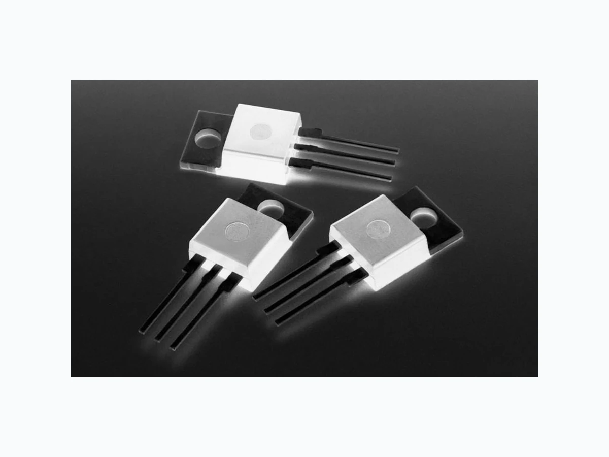
Q6012LTH1LEDTP overview
Q6012LTH1LEDTP is a component documented by Littelfuse. The PDF description identifies it as "Q6012LTH1LED series is designed to meet low load current characteristics typical in LED lighting applications." This guide condenses the most useful engineering information from the available PDF so that designers and sourcing teams can identify the checks that still need confirmation in the original document.
Datasheet snapshot
- Manufacturer: Littelfuse
- Part number: Q6012LTH1LEDTP
- Category: Microcontroller
- Datasheet length: 6 Pages
Key features noted in the PDF
- As l ow as 8mA max holding current
- UL r ecognized TO-220AB package
- 11 0°C rated junction temperature
- di/dt performance of A/μs
- QUADRAC version in cludes intergrated DIAC
- Pr ovides full control of light out put at the extreme low end of load conditions. 00V AC min isolation between mounting tab and active terminals Im proves margin of safe operatio.
Specifications and operating details
The following points were extracted from the PDF text. Check the associated conditions, notes and limits in the complete document before using a value in a design.
- 00V AC min isolation between mounting tab and active terminals Im proves margin of safe operation with less heat sinking required En able survivability of typically LED load operating characteristics Si mplicity of circuit design & layout.
- 0.1 µF (1) Reference test circuit in figure 7 and waveform in figure 8.
- Static Characteristics Symbol Test Conditions Value Unit VTM IT = 1 .41 x IT(rms) A; tp = 380μs MAX.
- Number of Cycles 100 1000 11 0 100 1000 Surge Current Duration -- Full Cycles Peak Surge (Non-repetitive) On-state Current (ITSM) – Amps Supply Frequency: 60Hz Sinusoidal Load: Resistive RMS On-State Current: [I T(RMS)]: Maximum Rated Valu.
- MT2 MT1 CT = 0.1 µF T VC 120 V 60 Hz RL ∆V+ ∆V- VC +VBO -VBO Figure 7: T est Circuit Figure 8: T est Circuit Waveform Revised: January 25, 2013 08:34 AM ©2013 Littelfuse, Inc Specifications are subject to change without notice.
- T eccor® brand Thyristors Reflow Condition Pb – Free assembly Pre Heat - Temperature Min (Ts(min)) 150°C - Temperature Max (Ts(max)) 200°C - Time (min to max) (ts) 60 – 180 secs Average ramp up rate (Liquidus Temp) (TL) to peak 5°C/second.
- Do not exceed 280°C Environmental Specifications Test Specifications and Conditions High T emperature Voltage Blocking MIL -STD-750: Method 1040, Condition A Rated V DRM (VAC-peak), 110°C, 1008 hours T emperature Cycling MIL -STD-750: Meth.
Topics covered by the datasheet
The document includes sections related to:
- DATASHEET SEARCH SITE
- Features
Engineering review checklist
- Check resistance value, tolerance, temperature coefficient and long-term stability over the operating range.
- Derate continuous power for ambient temperature and verify pulse or surge capability separately.
- Match the land pattern, termination finish and current-sense routing to the exact package option.
Always confirm values against the latest manufacturer-controlled datasheet, especially when qualifying a substitute or releasing a production BOM.
View the complete PDF and model record
Open the Q6012LTH1LEDTP datasheet and model details to review the complete PDF, document pages and available product information.
Source attribution
Adapted from the PDF associated with this DigiCamel model page.
Source model URL: https://www.digicamel.com/product.php?slug=q6012lth1ledtp-littelfuse