
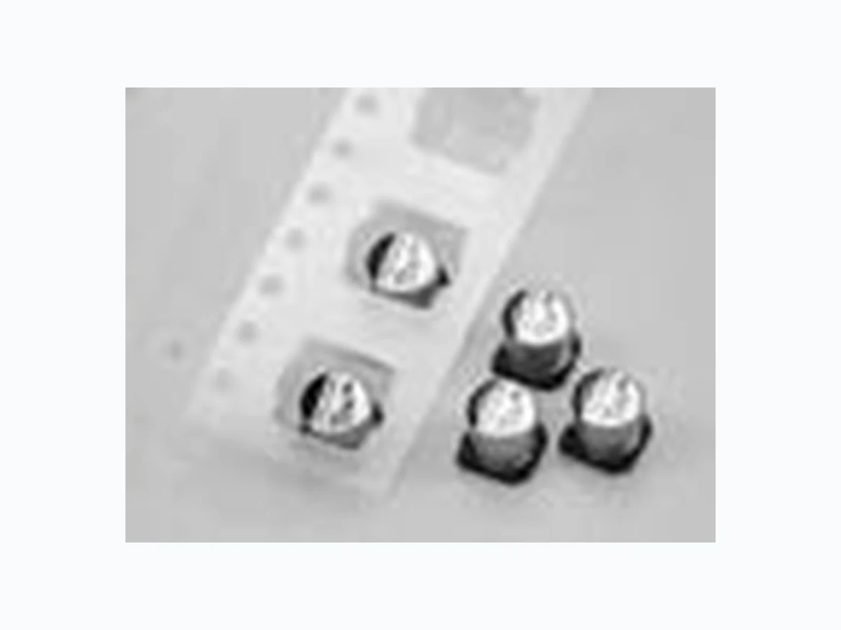
NACS221K106.3X5.5TR13F overview
NACS221K106.3X5.5TR13F is a component documented by NIC-Components Corp. The PDF description identifies it as "Surface Mount Aluminum Electrolytic Capacitors." This guide condenses the most useful engineering information from the available PDF so that designers and sourcing teams can identify the checks that still need confirmation in the original document.
Datasheet snapshot
- Manufacturer: NIC-Components Corp.
- Part number: NACS221K106.3X5.5TR13F
- Category: IC
- Datasheet length: 1 Pages
Key features noted in the PDF
- CYLINDRICAL V-CHIP CONSTRUCTION
- LOW PROFILE, 5.5mm MAXIMUM HEIGHT
- SPACE AND COST SAVINGS
- DESIGNED FOR REFLOW SOLDERING CHARACTERISTICS ** For higher voltages, 200V and 400V, see NACV series. MAXIMUM PERMISSIBLE RIPPLECURRENT (mA rms AT 120Hz AND 85OC) MAXIMUM ESR (Ω A.
Specifications and operating details
The following points were extracted from the PDF text. Check the associated conditions, notes and limits in the complete document before using a value in a design.
- MAXIMUM PERMISSIBLE RIPPLECURRENT (mA rms AT 120Hz AND 85OC) MAXIMUM ESR (Ω AT 120Hz AND 20OC) *Optional ± 10% (K) Tolerance available on most values.
- RoHS Compliant includes all homogeneous materials *See Part Number System for Details NACS 100 M 35V 4x5.5 TR 13 F RoHS Compliant 97% Sn (min.), 3% Bi (max.) 330mm (13”) Reel Tape & Reel Size in mm Working Voltage Tolerance Code M=20%, K=1.
- of zeros, “R” indicates decimal for values under 10µF Series PART NUMBER SYSTEM 0.3mm max.
- Dφ L + - I I W P A B STANDARD PRODUCT AND CASE SIZE Dφ xL (mm) RIPPLE CURRENT FREQUENCY CORRECTION FACTOR DIMENSIONS (mm) Rated Voltage Rating 6.3 ~ 50Vdc** Rated Capacitance Range 4.7 ~ 220µF Operating Temperature Range -40° ~ +85°C Capac.
- Leakage Current After 2 Minutes at 20°C 0.01CV or 3µA, whichever is greater Surge Voltage & Max.
- 85°C 2,000 Hours Capacitance Change Within ±25% of initial measured value Tanδ Less than 200% of specifi ed value Leakage Current Less than specifi ed value Cap. (µF) Working Voltage (Vdc) 6.3 10 16 25 35 50 4.7 - - - - - 18 10 - - - 20 20.
Topics covered by the datasheet
The document includes sections related to:
- FEATURES
Engineering review checklist
- Verify capacitance tolerance, rated voltage, temperature range and any DC-bias derating.
- Check ESR, ripple-current capability, lifetime and polarity requirements under worst-case conditions.
- Confirm package dimensions, land pattern and reflow or mounting limits for the selected ordering code.
Always confirm values against the latest manufacturer-controlled datasheet, especially when qualifying a substitute or releasing a production BOM.
View the complete PDF and model record
Open the NACS221K106.3X5.5TR13F datasheet and model details to review the complete PDF, document pages and available product information.
Source attribution
Adapted from the PDF associated with this DigiCamel model page.
Source model URL: https://www.digicamel.com/product.php?slug=nacs221k106-3x5-5tr13f-nic-components-corp