
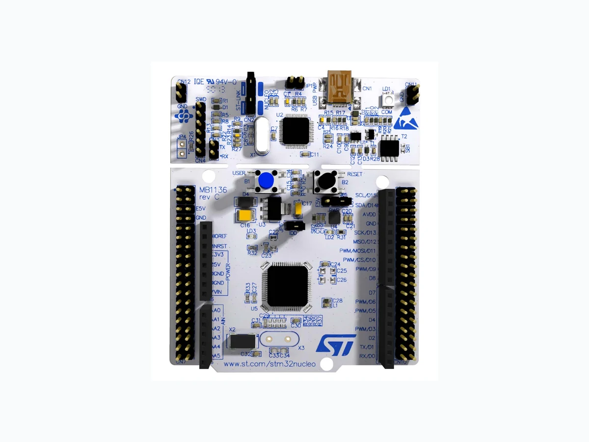
F303RE overview
F303RE is a component documented by List of Unclassifed Man. The PDF description identifies it as "STM32 Nucleo-64 boards." This guide condenses the most useful engineering information from the available PDF so that designers and sourcing teams can identify the checks that still need confirmation in the original document.
Datasheet snapshot
- Manufacturer: List of Unclassifed Man...
- Part number: F303RE
- Category: Microcontroller
- Datasheet length: 65 Pages
Key features noted in the PDF
- STM32 microcontroller with LQFP64 package
- Two types of extension resources – Arduino Uno Revision 3 connectivity – STMicroelectronics Morpho extension pin headers for full access to all STM32 I/Os
- mbed-enabled(a)
- On-board ST-LINK/V2-1 debugger/programmer with SWD connector – selection-mode switch to use the kit as a standalone ST-LINK/V2-1
- Flexible board power supply – USB VBUS – External VIN (7V<VIN<12V) supply volt age from Arduino connectors or ST Morpho connector – External 5V (E5V) supply voltage from ST Morpho.
- Three LEDs – USB communication (LD1), user LED (LD2), power LED (LD3)
- Two push buttons: USER and RESET
Specifications and operating details
The following points were extracted from the PDF text. Check the associated conditions, notes and limits in the complete document before using a value in a design.
- New features supported on ST-LINK/V2-1: – USB software re-enumeration – Virtual com port interface on USB – Mass storage interface on USB – USB power management request for more than 100 mA power on USB Features not supported on ST-LINK/V2.
- Using ST-LINK/V2-1 to program the STM32 on an external application 100 mA current to the host PC. Table 4.
- Debug connector CN4 (SWD) (continued)** the USB enumeration, the STM32 Nucleo board requires 300 mA of current to the Host PC.
- Power on the external power supply 7 V< VIN < 12 V to VIN, or 5 V for E5V.
- If more than 300 mA current is needed by the board, the PC may be damaged or the current supply can be limited by the PC.
- current is limited by the maximum current capability of the regulator U4 (500 mA max).
- LD3 PWR: the red LED indicates that the MCU part is powered and +5V power is available. Table 8. +3.3V eternal power source Hardware layout and configuration UM1724 B1 USER: the user button is connected to the I/O PC13 (pin 2) of the S.
Engineering review checklist
- Confirm supply rails, clock limits, memory size, peripheral mapping and I/O voltage compatibility.
- Check package pinout, boot configuration, programming interface and silicon-revision errata.
- Budget decoupling, thermal margin, startup timing and firmware recovery behavior before release.
Always confirm values against the latest manufacturer-controlled datasheet, especially when qualifying a substitute or releasing a production BOM.
View the complete PDF and model record
Open the F303RE datasheet and model details to review the complete PDF, document pages and available product information.
Source attribution
Adapted from the PDF associated with this DigiCamel model page.
Source model URL: https://www.digicamel.com/product.php?slug=f303re-list-of-unclassifed-man