
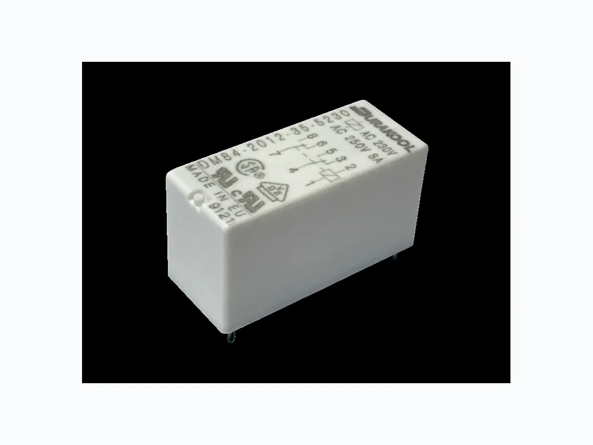
DM84-2012-35-1018 overview
DM84-2012-35-1018 is a component documented by Solid State Supplies. The PDF description identifies it as "PCB Power Relay." This guide condenses the most useful engineering information from the available PDF so that designers and sourcing teams can identify the checks that still need confirmation in the original document.
Datasheet snapshot
- Manufacturer: Solid State Supplies.
- Part number: DM84-2012-35-1018
- Category: IC
- Datasheet length: 3 Pages
Specifications and operating details
The following points were extracted from the PDF text. Check the associated conditions, notes and limits in the complete document before using a value in a design.
- switching current 5mA AgNi, 2mA AgNi/Au 5um, 10mA AgSnO2 20: AgNi Max.
- inrush current 15A AgSnO2 23: AgNi/Au 5m Rated current 8A 30: AgSnO2 Max.
- breaking capacity 0.3W AgNi, 0.05W AgNi/Au 5 um, 1W AgSnO2 Contact arrangement Initial resistance ≤ 100 mΩ max, at 0.1A/24VDC 12: 2C/O Max.
- operating frequency at rated load AC1 600 cycles/hour 21: 2NO no load AC1 72,000 cycles/hour Coil Environmental protection Must release voltage AC/DC AC ≥ 0.15Un, DC ≥ 0.1Un 3: In cover, IP67 (waterproof) Operating range See tables 1, 2 an.
- 7ms / 3ms cosφ See figure 2 DC L/R=40 ms > 105 0.15 A, 220VDC Mechanical life ops. > 3 x 10⁷ Environmental Environmental protection RTII IEC 61810-7 Cover protection IP40 or IP67 Solder bath temperature / time max.
- 270°C / 5s Ambient temperature operating AC -40 to +70°C, DC -40 to +85°C Notes: For AC loads this relay is designed for 50-60Hz standard industrial power and was tested according to AC1 category as defined by the IEC 60947-1 standard, cov.
- storage -40 to +85°C Shock resistance 20g Vibration resistance (NO/NC) 10g / 5g 10...150 Hz Dimensions L x W x H 29 x 12.7 x 15.7mm Weight approx.
Engineering review checklist
- Check resistance value, tolerance, temperature coefficient and long-term stability over the operating range.
- Derate continuous power for ambient temperature and verify pulse or surge capability separately.
- Match the land pattern, termination finish and current-sense routing to the exact package option.
Always confirm values against the latest manufacturer-controlled datasheet, especially when qualifying a substitute or releasing a production BOM.
View the complete PDF and model record
Open the DM84-2012-35-1018 datasheet and model details to review the complete PDF, document pages and available product information.
Source attribution
Adapted from the PDF associated with this DigiCamel model page.
Source model URL: https://www.digicamel.com/product.php?slug=dm84-2012-35-1018-solid-state-supplies