
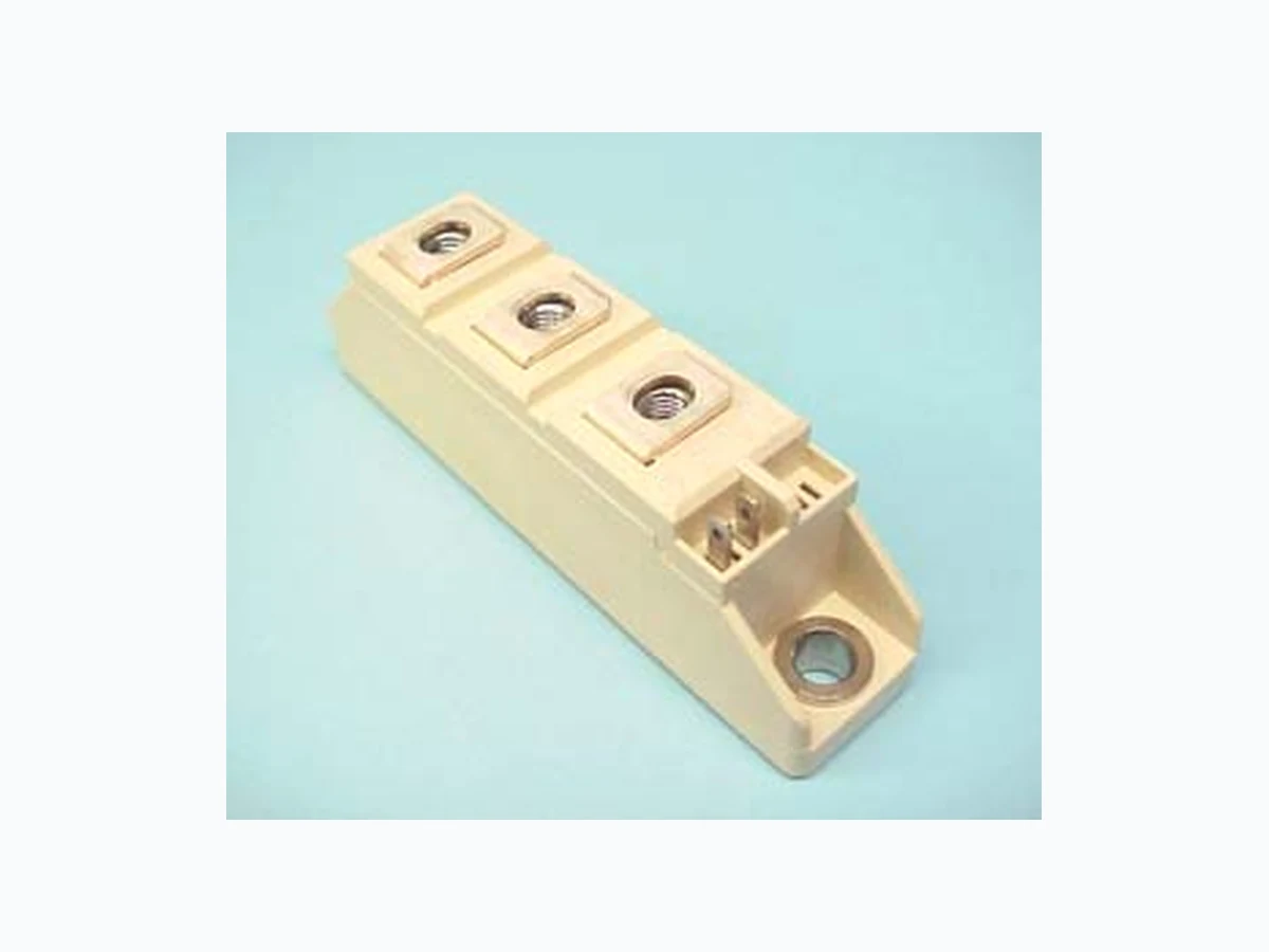
CD47__90B overview
CD47__90B is a component documented by Power Integrations, Inc. The PDF description identifies it as "POW-R-BLOK Dual SCR/Diode Isolated Module 90 Amperes / Up to 1800 Volts." This guide condenses the most useful engineering information from the available PDF so that designers and sourcing teams can identify the checks that still need confirmation in the original document.
Datasheet snapshot
- Manufacturer: Power Integrations, Inc...
- Part number: CD47__90B
- Category: IC
- Datasheet length: 4 Pages
Specifications and operating details
The following points were extracted from the PDF text. Check the associated conditions, notes and limits in the complete document before using a value in a design.
- V Isolation @ 25C Circuit to base, all terminals shorted together 50 – 60 Hz, 1 minute 50 – 60 Hz, 1 second Vrms Vrms 3000 3500 V V Information presented is based upon manufacturers testing and projected capabilities.
- Powerex, Inc., Hillis Street, Youngwood, Pennsylvania 15697 (724) 925-7272 POW-R-BLOKTM Dual SCR/Diode Isol ated Module Revision Date: 04/28/2009 CD42__90B CD47__90B Electrical Characteristics, TJ=25°C unless otherwise specified Characteri.
- Units Repetitive Peak Forward Leakage Current I DRM Up to 1800V, T J=125°C 20 mA Repetitive Peak Reverse Leakage Current I RRM Up to 1800V, T J=125°C 20 mA Peak On-State Voltage V TM / VFM I TM / IFM =300A 1.65 V Threshold Voltage, Low-lev.
- Units Thermal Resistance, Junction to Case DC Operation RΘJ-C Per Module, both conducting Per Junction, both conducting 0.14 0.28 °C/W °C/W Thermal Resistance, Case to Sink Lubricated RΘC-S Per Module 0.1 °C/W Powerex, Inc., Hillis Street.
- Case Temperature - Tcase -°C (Rectangular Waveform) Maximum On-State Forward Voltage Drop 0.5 1.5 2.5 3.5 10 100 1000 Instantaneous On-State Current - Itm / Ifm - Amperes On-State Voltage - Vtm / Vfm - Volts ( Tj = 125 °C ) Maximum Transie.
Engineering review checklist
- Confirm repetitive reverse voltage, average forward current, surge current and leakage at the intended temperature.
- Check forward-voltage loss and reverse-recovery behavior at the actual current and switching frequency.
- Review package thermal resistance, copper area, polarity marking and transient derating before layout release.
Always confirm values against the latest manufacturer-controlled datasheet, especially when qualifying a substitute or releasing a production BOM.
View the complete PDF and model record
Open the CD47__90B datasheet and model details to review the complete PDF, document pages and available product information.
Source attribution
Adapted from the PDF associated with this DigiCamel model page.
Source model URL: https://www.digicamel.com/product.php?slug=cd47-90b-power-integrations-inc