
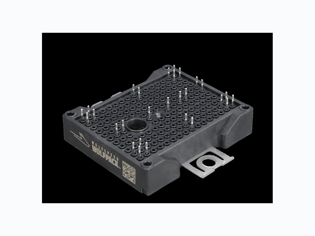
CAB6R0A23GM4 overview
CAB6R0A23GM4 is a component documented by WOLFSPEED, INC. The PDF description identifies it as "2300 V, 6.0 mΩ, Silicon Carbide, Half-Bridge Module Rev. 2, Nov 2024." This guide condenses the most useful engineering information from the available PDF so that designers and sourcing teams can identify the checks that still need confirmation in the original document.
Datasheet snapshot
- Manufacturer: WOLFSPEED, INC.
- Part number: CAB6R0A23GM4
- Category: IC
- Datasheet length: 12 Pages
Specifications and operating details
The following points were extracted from the PDF text. Check the associated conditions, notes and limits in the complete document before using a value in a design.
- CAB6R0A23GM4, CAB6R0A23GM4T Technical Features Ultra-Low Loss High Frequency Operation Zero Turn-Off Tail Current from MOSFET Normally-Off, Fail-Safe Device Operation Aluminium Nitride Substrate Optional Pre-Applied Thermal Interface Mater.
- MOSFET Characteristics (Per Position) (TVJ = 25 °C unless otherwise specified) Parameter Symbol Min.
- Unit Test Conditions Note Drain-Source Breakdown Voltage V(BR)DSS 2300 V VGS = 0 V, TVJ = -40 °C Gate Threshold Voltage VGS(th) 1.8 2.5 4.0 VDS = VGS, ID = 95 mA Zero Gate Voltage Drain Current IDSS 13 750 µA VGS = 0 V, VDS = 2300 V Gate-S.
- 314.3 VGS = 15 V, ID = 200 A, TVJ = 150 °C Transconductance gfs 210 S VDS = 20 V, ID = 200 A Fig.
- 13Turn-Off Switching Energy, TVJ = 25 °C TVJ = 125 °C TVJ = 150 °C EOff 3.3 3.6 3.7 Internal Gate Resistance RG(int) 1.3 Ω f = 100 kHz Input Capacitance Ciss 30.5 nF VGS = 0 V, VDS = 1500 V, VAC = 25 mV, f = 100 kHz Fig.
- 9Output Capacitance Coss 0.50 Reverse Transfer Capacitance Crss 40 pF Gate to Source Charge QGS 230 nC VDS = 1500 V, VGS = -4 V/15 V, ID = 200 A, Per IEC60747-8-4 pg 21 Gate to Drain Charge QGD 195 Total Gate Charge QG 735 FET Thermal Resi.
- Unit Test Conditions Notes Body Diode Forward Voltage VSD 5.8 V VGS = -4 V, ISD = 200 A Fig.
Engineering review checklist
- Check voltage, continuous and pulsed current, safe operating area and junction-temperature limits.
- Evaluate conduction and switching losses using the specified drive conditions rather than headline ratings.
- Confirm pinout, package thermal path, gate or base protection and transient derating in the final circuit.
Always confirm values against the latest manufacturer-controlled datasheet, especially when qualifying a substitute or releasing a production BOM.
View the complete PDF and model record
Open the CAB6R0A23GM4 datasheet and model details to review the complete PDF, document pages and available product information.
Source attribution
Adapted from the PDF associated with this DigiCamel model page.
Source model URL: https://www.digicamel.com/product.php?slug=cab6r0a23gm4-wolfspeed-inc