
DATASHEET SEARCH SITE
Document overview
- Manufacturer or author: Provided By digicamel.com
- PDF pages: 7
Technical content
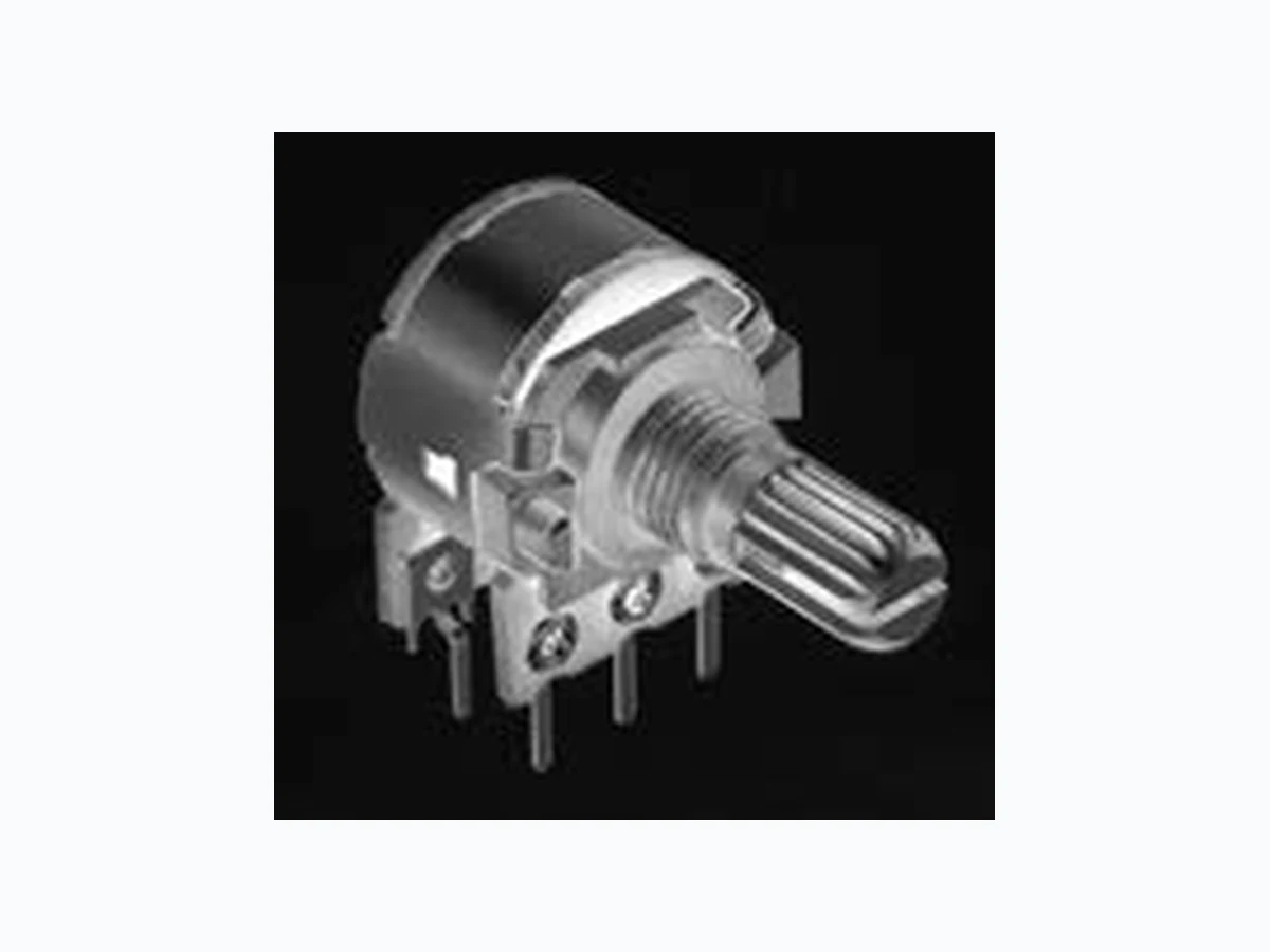
A wide range of versatile products applicable for various types of control 16mm Size Metal Shaft TypeRK163 Refer to P.334 for other specifications. Refer to P.335 for attached parts. Refer to P.336 for ordering products not listed. Refer to P.349 for soldering conditions Other varieties are also available. Refer to "Other Specifications" (P.334). Note Product Line Number of resistor elements Mounting direction Shaft type Length of the shaft L1(mm) Center detent Total resistance (k Ω) Resistance taper Minimum order unit (pcs.) Japan Expert Drawing No. Single-unit Dual-unit for tone Dual-unit for vol. Horizontal type Flat Serrated Flat Serrated Flat Serrated Terminal style For PC board Lead For PC board For PC board Lead Without Without With 15A 15A 15A Products No. RK1631110TBK RK1631110TT3 RK1631110U1Q RK1631110TNP RK1631110TTU RK1631110U0Q RK1631210AWN RK16312101A2 RK1631210AX9 RK16312A0B85 RK16312A0BKH RK16312A0BKR 600 1,20 0 200 400 600 1,20 0 200 400 600 1,20 0 ■ Typical Specifications Items Specifications Total resistance tolerance ±20% Maximum operating voltage 150V AC, 5V DC Total rotational angle 300° ±3° Rotational torque 3 to 25mN ・ m Operating life 15,000 cycles Operating temperature range −10℃ to +70℃ Packing Specifications Bulk Terminal style Number of packages (pcs.) Export package measurements (mm)1 case /Japan 1 case /export packing For PC board 600 1,20 0 326×532×386 Lead 200 400 270×360×155
Dimensions Unit:mm 10.5 4.5 12.5 60˃ ø16 2R1 7.5 0.31.5 11 23 M7G0.75 LB Shaft shown in full C.C.W. position 4.5 12.1 ø16 15 1 4 12.5 7.5 1.5 0.3 60˚ 321 M7x0.75 R1 R2 Shaft shown in full CCW position No. Photo Style PC board mounting hole dimensions (Viewed from mounting side) Single-shaft, single-unit RK163111 4.5 13.5 60ƅ 10.5 20 RK1631110TNP-RV2.EPS 12 3 7.5 1.5 0.3 M7ʷ0.75 Shaft shown in full CCW position ø16 Single-shaft, single-unit Lead terminal RK163111 0.7 ø16 15 7.5 1.5 12 3 RK1631110TTU-RV3-ਤ.EPS 12.5 0.35 2 M7ʷ0.75 10.5 Shaft slot is optional angle. Single-shaft, single-unit RK163111 ʷ Single-shaft, single-unit Lead terminal RK163111 Single-shaft, dual-unit RK163121(For tone) RK16312A(For volume) ʷ ਤ Single-shaft, dual-unit RK163121(For tone) RK16312A(For volume) 15 20 5 7 7 12 LB 20 25L1 RK163/16mm Size Metal Shaft Type 3.8 5 5 Mounting surface 3-ø1.2 hole 5 3.8 Mounting surface 6-ø1.2 hole RK1631110TTU-RV3-ੇ๏ਤ.EPS 3.8 3–ø1.2 hole Mounting surface 6–ø1.2 hole 5 5 3.8 RK163120-2-RV5-ੇ๏ਤ.EPS Mounting surface
Applications
Refer to P.335 for attached parts. Refer to P.336 for ordering products not listed. In addition to the products listed, we can accommodate the follow specifications. Total Resistance Variety Total resistance (kΩ) 5 10 20 50 100 200 Single-shaft, single-unit Single-shaft, dual-unit RK16311 RK16312 General General or Volume and tone control Center Model Detent variety Resistance Taper Resistance taper 15A 1B 3B 15 C Dimensions of Shaft 1) 18 teeth serrated type LB R1 18 teeth Serrated 0.7 Not specified slotting angle M7G0.75 Y Y XX Shaft shown in full CCW position 90˚ ¡The serration angle shall be as shown. 2) Flat type LB Shaft shown in full CCW position 4.5 60˚ M7G0.75 3) Slotted type LB C0.5 Shaft shown in full CCW position 60˚1.6 M7G0.75 Die-casting shaft LB R1 Unit:mm Unit:mm Unit:mm LB LB Detail dimensions Detail dimensions Detail dimensions Product Specifications and Applications Type Marked are specifications recommended by Alps. Note 16mm Size Metal Shaft Type / Other Specifications
The following parts are included with the product. Nut Washer M7×0.75 ø12 ø7.2 0.5 16mm Size Metal Shaft Type / Attached Parts Unit:mm
21 —21 Code Detent Model type Code 111 121 Model type Single-unit 12A Dual-unit for vol. Dual-unit for tone Shaft type Code F Shaft type Flat S Slotted K Serrated Terminal Style Code P Terminal style For PC board L Lead terminal Resistance taper Code A B Resistance taper 15A Resistance taper 15 C Code V C Length of the shaft L1 (mm) Code Length of the shaft 20 20 Code Length of the shaft Total resistance Code 502 103 Total resistance (k Ω) 203 20 Total resistance (k Ω) 100 200 Code 503 10 4 204 R K 1 6 3 1 1 1 0 F 2 0 C 0 B 1 0 3 P B: For tone & general (model type 111, 121) V: For vol. (model type 111, 12A) Marked are specifications recommended by Alps. Note 100 0 10 20 30 40 50 60 70 80 90 Output volt.across term.2-3 Input volt. across term. 1-3 100 C(15C) G 100 (%) J Rotation travel (%) Term."1" Term."3"J 100 0 100 90 80 70 60 50 40 30 20 10 Rotation travel (%) Term."1" Term."3" Output volt.across term.1-2 Input volt. across term. 1-3 G 100 (%) B(1B) V(vol.control)(3B) J J A(15A) When ordering product varieties that are not listed, specify referring to the examples below. 16mm Size Metal Shaft Type / Ordering Products Not Listed
Metal Shaft Potentiometers Type 16mm size 20mm size 27mm size 50mm size Rotary motor-driven Series RK163 RK203/EC20A RK271 RK501 RK168 Single-shaft Number of resistor elements Single/dual Single Single/dual/quad Dual/quad Dual/quad/5-ganged/6-ganged Photo Terminal mounting Horizontal Vertical Horizontal Fixing method of bushing Bushing screw clamp Operating temperature range − 10℃ to + 70℃RK203 : −40℃ to +85℃ Operating life 1 5,000 cycles 30,000 cycles 1 5,000 cycles Available for automotive use — 〇 — — — Life cycle (availability) Electrical performance Total resistance (k Ω) 5, 10, 20, 50, 100, 200 10 5, 10, 20, 50, 100, 250 10, 20, 50, 100 Resistance taper 15A, 1B, 3B, 15C B 15A , 3B Rated Power 0.1W 0.05W (15A) 0.05W 0.1W 0.05W Residual resistance R≦10kΩ 20Ω max. 10kΩ<R≦50kΩ 30Ω max. 50kΩ<R<3MΩ Nominal total resistance of 0.1% o r less % — R≦10kΩ 20Ω max. 10kΩ<R<50kΩ 30Ω max. 50kΩ≦R Nominal total resistance of 0.1% o r less % — — Maximum attenuation (Volume control) 5kΩ≦R< 10kΩ 7 0dB min. 10kΩ≦R< 50kΩ 8 0dB min. 50kΩ≦R<100kΩ 9 0dB min. 0kΩ≦R 10 0dB min. 5kΩ≦R< 10kΩ 7 0dB min. 10kΩ≦R< 50kΩ 8 0dB min. 50kΩ≦R<100kΩ 9 0dB min. 100kΩ≦R 100dB min. 120dB m in. 5kΩ≦R< 10kΩ 7 0dB min. 10kΩ≦R< 50kΩ 8 0dB min. 50kΩ≦R<100kΩ 9 0dB min. 100kΩ≦R 100dB min. Gang error applicable to Dual-unit parts for audio volume control purposes −40dB to 0dB 3dB max. — − 70dB to −60dB 3dB max. −60dB to 0dB 2dB max. − 100dB to 0dB 2dB max. −60dB to −40dB 5dB max. −40dB to 0dB 3dB max. Insulation resistance 100MΩ min. 500V DC 10MΩ min. 250V DC 100MΩ min. 500V DC 100MΩ min. 250V DC Voltage proof 500V AC f or 1minute 300V AC f or 1minute 5 0 0V A C f or 1minute 300V AC f or 1minute Center-taps Without Mechanical performance Detent Without, Center, 21, 31, 41 17 Without, Center, 21, 31, 41 Without Push-pull strength 100N ma x . 1 50N max. 100N ma x . Vibration 10 to 55 to 10Hz/min., the amplitude is 1.5mm for all the frequencies, in the 3 direction of X, Y and Z for 2 hours respectively Shaft style Serrated type, Flat type, Slotted type Flat type Slotted type, Flat type Slotted type Flat type Terminal style Insertion, Lead Insertion Attached switch — EC20A: Momentary push switch — — — Page 332 337 340 344 346 Potentiometers Cautions Potentiometers Resistance Taper Note ○ Indicates applicability to some products in the series.
Reference for Manual Soldering Example of Reflow Soldering Condition Reference for Dip Soldering 300 200 100 A B C Time (s) G max. F max. H max. E max. Room temperature Temperature (˚C ) Pre-heating D Series Tip temperature Soldering time No. of solders RK09L, RK097 350℃ max. 3s max. 1 time RK203 300℃ max. 3s max. 1 time RK119 3 5 0 ±10 ℃ 3 s 1 time RK271 350℃ max. 5s max. 1 time RK501 3 5 0 ±10 ℃ 5 s 1 time RK163 350℃ max. 5s max. 1 time RK168 Potentiometer terminal 300℃ max. 3s max. 1 time Motor terminal 350℃ max. 2s max. 1 time Series Preheating Dip soldering No. of soldersSoldering surface temperature Heating time Soldering temperature Soldering time RK09L, RK097, RK203 100℃ ma x . 2 min. max. 260±5℃ 5±1s 2 time max. RK501 12 0 ±10 ℃ 2 min. max. 260±5℃ 5±1s 2 time Series A B C D E F G H No. of reflows RK119 260℃ 230℃ 180℃ 15 0 ℃ 2 min. 3s 40s 4 min. 2 time max. 1. When using an infrared reflow oven, solder may sometimes not be applied. Be sure to use a hot air reflow oven or at type that uses infrared rays in combination with hot air. 2. The temperatures given above are the maximum temperatures at the terminals of the potentiometer when employing a hot air reflow method. The temperature of the PC board and the surface temperature of the potentiometer may vary greatly depending on the PC board material, its size and thickness. Ensure that the surface temperature of the potentiometer does not rise to 250℃ or greater. 3. Conditions vary to some extent depending on the type of reflow bath used. Be sure to give due consideration to this prior to use. Notes Temperature profile Metal Shaft Potentiometers / Soldering Conditions