

 Download PDF
DATASHEET SEARCH SITE
Document overview
- PDF pages: 42
Technical content
Page 1
8V to 36Vin Cool-Power ZVS Buck Regulator Family
Description
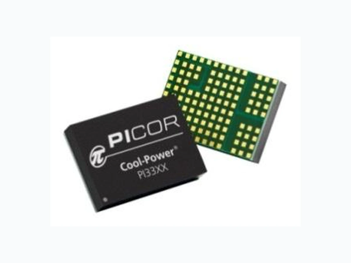
The PI33XX is a family of high efficiency, wide input range DC-DC ZVS-Buck regulators integrating controller, power switches, and support components all within a high density System-in-Package (SiP). The integration of a high performance Zero-Voltage Switching (ZVS) topology, within the PI33XX series, increases point of load performance providing best in class power efficiency. The PI33XX requires only an external inductor and minimal capacitors to form a complete DC-DC switching mode buck regulator.
| Device | Output Voltage | Iout Max | |
|---|---|---|---|
| Set | Range | ||
| PI3311-X0-LGIZ | 1.0V | 1.0 to 1.4V | 10A |
| PI3318-X0-LGIZ | 1.8V | 1.4 to 2.0V | 10A |
| PI3312-X0-LGIZ | 2.5V | 2.0 to 3.1V | 10A |
| PI3301-X0-LGIZ | 3.3V | 2.3 to 4.1V | 10A |
| PI3302-X0-LGIZ | 5.0V | 3.3 to 6.5V | 10A |
| PI3303-X0-LGIZ | 12V | 6.5 to 13.0V | 8A |
| PI3305-X0-LGIZ | 15V | 10.0 to 16.0V | 8A |
Table 1 - PI33XX-X0 Portfolio.
The ZVS architecture also enables high frequency operation while minimizing switching losses and maximizing efficiency. The high switching frequency operation reduces the size of the external filtering components, improves power density, and enables very fast dynamic response to line and load transients. The PI33XX series sustains high switching frequency all the way up to the rated input voltage without sacrificing efficiency and, with its 20ns minimum on-time, supports large step down conversions up to 36Vin.
I2C is a trademark of NXP Semiconductors
Features
High Efficiency ZVS-Buck Topology Wide input voltage range of 8V to 36V Very-Fast transient response High accuracy pre-trimmed output voltage User adjustable soft-start & tracking Power-up into pre-biased load (select versions) Parallel capable with single wire current sharing Input Over/Under Voltage Lockout (OVLO/UVLO) Output Overvoltage Protection (OVP) Over Temperature Protection (OTP) Fast and slow current limits -40°C to 125°C operating range (TJ) Optional I2C functionality & programmability: Vout margining Fault reporting Enable and SYNCI pin polarity Phase delay (interleaving multiple regulators)
Applications
High efficiency systems Computing, Communications, Industrial, Automotive Equipment High voltage battery operation
Package Information
800 735.6200 11/2012 Page 1 of 42
Page 2
Contents
Order Information ...................................................... 3
Pin Description ............................................................ 4
Package Pin-Out .......................................................... 4
Absolute Maximum Ratings ........................................ 5
PI3311-X0 (1.0 Vout) Electrical Characteristics........... 6
PI3318-X0 (1.8 Vout) Electrical Characteristics........... 9
PI3312-X0 (2.5 Vout) Electrical Characteristics......... 12
PI3301-X0 (3.3 Vout) Electrical Characteristics......... 16
PI3302-X0 (5.0 Vout) Electrical Characteristics......... 20
PI3303-X0 (12.0 Vout) Electrical Characteristics ...... 24
PI3305-X0 (15.0 Vout) Electrical Characteristics ...... 28
Functional Description .............................................. 32
ENABLE (EN) ......................................................... 32
Switching Frequency Synchronization.................. 32
Output Voltage Trim............................................. 32
Soft-Start .............................................................. 32
Remote Sensing .................................................... 33
Output Current Limit Protection .......................... 33
Input Under-Voltage Lockout ............................... 33
Input Over Voltage Lockout ................................. 33
Output Over Voltage Protection .......................... 33
Over Temperature Protection .............................. 33
Pulse Skip Mode (PSM) ........................................ 33
Variable Frequency Operation ............................. 34
Parallel Operation ................................................ 34
I2C Interface Operation ....................................... 34
Application Description ............................................. 35
Output Voltage Trim ............................................ 35
Soft-Start Adjust and Tracking ............................. 36
Inductor Pairing ................................................... 36
Thermal Derating ................................................. 36
Filter Considerations ............................................ 38
Layout Guidelines ...................................................... 39
Recommended PCB Footprint and Stencil ................ 40
Package Drawings ..................................................... 41
Warranty ................................................................... 42
800 735.6200 11/2012 Page 2 of 42
Page 3
Order Information
| Cool-Power | Output Range | Iout Max | Package | Transport Media | |
|---|---|---|---|---|---|
| Set | Range | ||||
| PI3311-00-LGIZ | 1.0V | 1.0 to 1.4V | 10A | 10mm x 14mm 123-pin LGA | TRAY |
| PI3318-00-LGIZ | 1.8V | 1.4 to 2.0V | 10A | 10mm x 14mm 123-pin LGA | TRAY |
| PI3312-00-LGIZ | 2.5V | 2.0V to 3.1V | 10A | 10mm x 14mm 123-pin LGA | TRAY |
| PI3301-00-LGIZ | 3.3V | 2.3 to 4.1V | 10A | 10mm x 14mm 123-pin LGA | TRAY |
| PI3302-00-LGIZ | 5.0V | 3.3 to 6.5V | 10A | 10mm x 14mm 123-pin LGA | TRAY |
| PI3303-00-LGIZ | 12V | 6.5 to 13.0V | 8A | 10mm x 14mm 123-pin LGA | TRAY |
| PI3305-00-LGIZ | 15V | 10.0 to 16.0V | 8A | 10mm x 14mm 123-pin LGA | TRAY |
| Higher Current Versions (Refer to PI33XX-X1-LGIZ Datasheet) | |||||
| PI3311-01-LGIZ | 1.0V | 1.0 to 1.4V | 15A | 10mm x 14mm 123-pin LGA | TRAY |
| PI3318-01-LGIZ | 1.8V | 1.4 to 2.0V | 15A | 10mm x 14mm 123-pin LGA | TRAY |
| PI3312-01-LGIZ | 2.5V | 2.0 to 3.1V | 15A | 10mm x 14mm 123-pin LGA | TRAY |
| PI3301-01-LGIZ | 3.3V | 2.3 to 4.1V | 15A | 10mm x 14mm 123-pin LGA | TRAY |
| I2C Functionality & Programmability | |||||
| PI3311-20-LGIZ | 1.0V | 1.0 to 1.4V | 10A | 10mm x 14mm 123-pin LGA | TRAY |
| PI3318-20-LGIZ | 1.8V | 1.0 to 1.4V | 10A | 10mm x 14mm 123-pin LGA | TRAY |
| PI3312-20-LGIZ | 2.5V | 2.0 to 3.1V | 10A | 10mm x 14mm 123-pin LGA | TRAY |
| PI3301-20-LGIZ | 3.3V | 2.3 to 4.1V | 10A | 10mm x 14mm 123-pin LGA | TRAY |
| PI3302-20-LGIZ | 5.0V | 3.30 to 6.5V | 10A | 10mm x 14mm 123-pin LGA | TRAY |
| PI3303-20-LGIZ | 12V | 6.5 to 13.0V | 8A | 10mm x 14mm 123-pin LGA | TRAY |
| PI3305-20-LGIZ | 15V | 10.0 to 16.0V | 8A | 10mm x 14mm 123-pin LGA | TRAY |
| PI3311-21-LGIZ | 1.0V | 1.0 to 1.4V | 15A | 10mm x 14mm 123-pin LGA | TRAY |
| PI3318-21-LGIZ | 1.8V | 1.4 to 2.0V | 15A | 10mm x 14mm 123-pin LGA | TRAY |
| PI3312-21-LGIZ | 2.5V | 2.0 to 3.1V | 15A | 10mm x 14mm 123-pin LGA | TRAY |
| PI3301-21-LGIZ | 3.3V | 2.3 to 4.1V | 15A | 10mm x 14mm 123-pin LGA | TRAY |
800 735.6200 11/2012 Page 3 of 42
Page 4
Pin Description
| Name | Number | Description |
|---|---|---|
| SGND | Block 1 | Signal ground: Internal logic ground for EA, TRK, SYNCI, SYNCO, ADJ and I2C (options) communication returns. SGND and PGND are star connected within the regulator package. |
| PGND | Block 2 | Power ground: VIN and VOUT power returns |
| VIN | Block 3 | Input voltage: and sense for UVLO, OVLO and feed forward ramp |
| VOUT | Block 5 | Output voltage: and sense for power switches and feed-forward ramp |
| VS1 | Block 4 | Switching node: and ZVS sense for power switches |
| PGD | A1 | Parallel Good: Used for parallel timing management intended for lead regulator. |
| EAO | A2 | Error amp output: External connection for additional compensation and current sharing. |
| EN | A3 | Enable Input: Regulator enable control. Asserted high or left floating – regulator enabled; Asserted low, regulator output disabled. Polarity is programmable via I2C interface. |
| REM | A5 | Remote Sense: High side connection. Connect to output regulation point. |
| ADJ | B1 | Adjust input: An external resistor may be connected between ADJ pin and SGND or VOUT to trim the output voltage up or down. |
| TRK | C1 | Soft-start and track input: An external capacitor may be connected between TRK pin and SGND to decrease the rate of rise during soft-start. |
| NC | K3, A4 | No Connect: Leave pins floating. |
| SYNCO | K4 | Synchronization output: Outputs a low signal for ½ of the minimum period for synchronization of other converters. |
| SYNCI | K5 | Synchronization input: Synchronize to the falling edge of external clock frequency. SYNCI is a high impedance digital input node and should always be connected to SGND when not in use. |
| SDA | D1 | Data Line: Connect to SGND for PI33XX-10 and -11. For use with PI33XX-20 and -21 only. |
| SCL | E1 | Clock Line: Connect to SGND for PI33XX-10 and -11. For use with PI33XX-20 and -21 only. |
| ADR1 | H1 | Tri-state Address : No connect for PI33XX-10 and -11. For use with PI33XX-20 and -21 only. |
| ADR0 | G1 | Tri-state Address : No connect for PI33XX-10 and -11. For use with PI33XX-20 and -21 only. |
Package Pin-Out
PGND Block 2
1 2 3 4 5 6 7 8 9 10 11 12 13 14
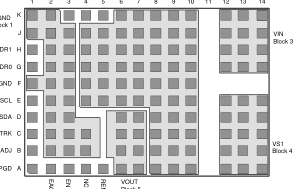
SGND Block 1
SGND
Block 5
123-Lead LGA (10mm x 14mm) Top view
Block 1: B2-4, C2-4, D2-3, E2-3, F1-3, G2-3, H2-3, J1-3, K1-2
Block 2: A8-10, B8-10, C8-10, D8-10, E4-10, F4-10, G4-10, H4-10, J4-10, K6-10
Block 3: G12-14, H12-14, J12-14, K12-14
Block 4: A12-14, B12-14, C12-14, D12-14, E12-14,
Block 5: A6-7, B6-7, C6-7, D6-7
800 735.6200 11/2012 Page 4 of 42
Page 5
Absolute Maximum Ratings
Notes: At 25°C ambient temperature. All voltage nodes are referenced to PGND.
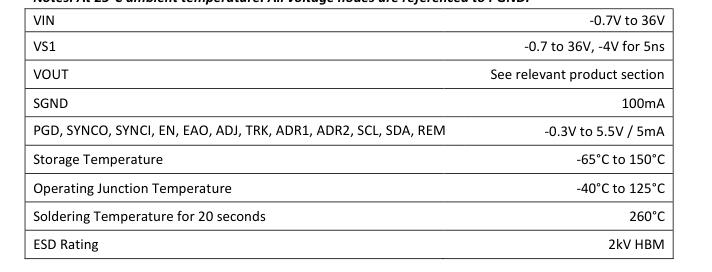
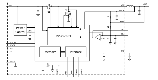
Figure 1: Simplified Block Diagram
(I2C pins SCL, SDA, ADR0, and ADR1 only active for PI33XX-20 and PI33XX-21 versions)
800 735.6200 11/2012 Page 5 of 42
Page 6
PI3311-X0 (1.0 Vout) Electrical Characteristics
Specifications apply for -40C < TJ < 125C, Vin =24V, L1=125nH (Note 1) unless other conditions are noted.
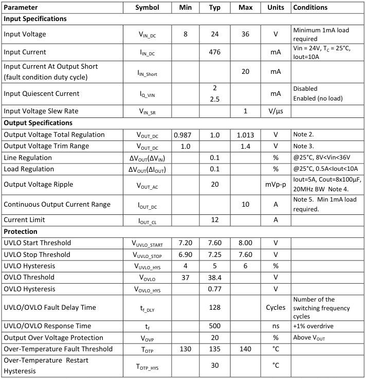
Note 1: All parameters reflect regulator and inductor system performance. Measurements were made using a standard PI33XX evaluation board with 3x4” dimensions and 4 layer, 2oz copper. Refer to inductor pairing table within Application Description section for specific inductor manufacturer and value. Note 2: Regulator is assured to meet performance specifications by design, test correlation, characterization, and/or statistical process control.
Note 3: Output current capability may be limited and other performance may vary from noted electrical characteristics when switching frequency or Vout is modified. Note 4: Refer to Output Ripple plots. Note 5: Refer to Load Current vs. Ambient Temperature curves. Note 6: Refer to Switching Frequency vs. Load current curves.
800 735.6200 11/2012 Page 6 of 42
Page 7
PI3311-X0 (1.0 Vout) Electrical Characteristics
Specifications apply for -40C < TJ < 125C, Vin =24V, L1=125nH (Note 1) unless other conditions are noted.
| Parameter | Symbol | Min | Typ | Max | Units | Conditions |
|---|---|---|---|---|---|---|
| Timing | ||||||
| Switching Frequency | f S | 500 | kHz | Note 6. | ||
| Fault Restart Delay | t FR_DLY | 30 | ms | |||
| Sync In (SYNCI) | ||||||
| Synchronization Frequency Range | ∆f SYNCI | 50 | 110 | % | Relative to set switching frequency. Note 3. | |
| SYNCI Threshold | V SYNCI | 2.5 | V | |||
| Sync Out (SYNCO) | ||||||
| SYNCO High | V SYNCO_HI | 4.5 | V | Source 1mA | ||
| SYNCO Low | V SYNCO_LO | 0.5 | V | Sink 1mA | ||
| SYNCO Rise Time | t SYNCO_RT | 10 | 20 | ns | 20pF load | |
| SYNCO Fall Time | t SYNCO_FT | 10 | 20 | ns | 20pF load | |
| Soft Start And Tracking | ||||||
| TRK Active Range (Nominal) | V TRK | 0 | 1 | V | ||
| TRK Enable Threshold | V TRK_OV | 20 | 40 | 60 | mV | |
| Charge Current (Soft – Start) | I TRK | -70 | -50 | -30 | µA | |
| Discharge Current (Fault) | I TRK_DIS | 6.8 | mA | |||
| Soft-Start Time | t SS | 2.2 | 2.6 | ms | C = 0 TRK | |
| Enable | ||||||
| High Threshold | V EN_HI | 0.9 | 1 | 1.1 | V | |
| Low Threshold | V EN_LO | 0.7 | 0.8 | 0.9 | V | |
| Threshold Hysteresis | V EN_HYS | 100 | 200 | 300 | mV | |
| Enable Pull-Up Voltage (floating, unfaulted) | V EN_PU | 2 | V | |||
| Enable Pull-Down Voltage (floating, faulted) | V EN_PD | 0 | V | |||
| Source Current | I EN_SO | -50 | uA | |||
| Sink Current | I EN_SK | 50 | uA | |||
Note 1: All parameters reflect regulator and inductor system performance. Measurements were made using a standard PI33XX evaluation board with 3x4” dimensions and 4 layer, 2oz copper. Refer to inductor pairing table within Application Description section for specific inductor manufacturer and value. Note 2: Regulator is assured to meet performance specifications by design, test correlation, characterization, and/or statistical process control.
Note 3: Output current capability may be limited and other performance may vary from noted electrical characteristics when switching frequency or Vout is modified. Note 4: Refer to Output Ripple plots. Note 5: Refer to Load Current vs. Ambient Temperature curves. Note 6: Refer to Switching Frequency vs. Load current curves.
800 735.6200 11/2012 Page 7 of 42
Page 8
PI3311-X0 (1.0 Vout) Electrical Characteristics
Efficiency at 25°C
Transient Response: 2A to 7A, at 5A/µs
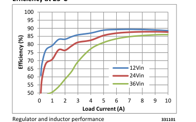
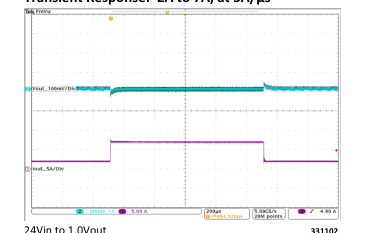
24Vin to 1.0Vout 331102 Cout = 8X 100µF Ceramic
Output Ripple: 24Vin, 1.0Vout at 10A
Short Circuit Test
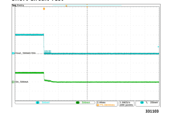
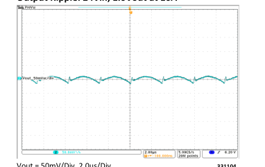
Vout = 50mV/Div, 2.0us/Div 331104 Cout = 8X 100µF Ceramic
Output ripple: 24Vin, 1.0Vout at 5A
Switching Frequency vs. Load Current
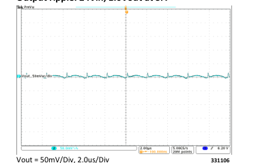
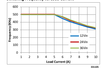
Cout = 8X 100µF Ceramic
800 735.6200 11/2012 Page 8 of 42
Page 9
PI3318-X0 (1.8 Vout) Electrical Characteristics
Specifications apply for -40C < TJ < 125C, Vin =24V, L1=155nH (Note 1) unless other conditions are noted.
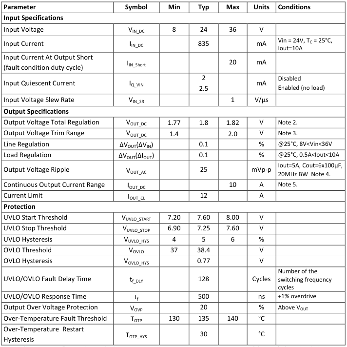
Note 1: All parameters reflect regulator and inductor system performance. Measurements were made using a standard PI33XX evaluation board with 3x4” dimensions and 4 layer, 2oz copper. Refer to inductor pairing table within Application Description section for specific inductor manufacturer and value. Note 2: Regulator is assured to meet performance specifications by design, test correlation, characterization, and/or statistical process control.
Note 3: Output current capability may be limited and other performance may vary from noted electrical characteristics when switching frequency or Vout is modified. Note 4: Refer to Output Ripple plots. Note 5: Refer to Load Current vs. Ambient Temperature curves. Note 6: Refer to Switching Frequency vs. Load current curves.
800 735.6200 11/2012 Page 9 of 42
Page 10
PI3318-X0 (1.8 Vout) Electrical Characteristics
Specifications apply for -40C < TJ < 125C, Vin =24V, L1=155nH (Note 1) unless other conditions are noted.
| Parameter | Symbol | Min | Typ | Max | Units | Conditions |
|---|---|---|---|---|---|---|
| Timing | ||||||
| Switching Frequency | f S | 600 | kHz | Note 6. | ||
| Fault Restart Delay | t FR_DLY | 30 | ms | |||
| Sync In (SYNCI) | ||||||
| Synchronization Frequency Range | ∆f SYNCI | 50 | 110 | % | Relative to set switching frequency. Note 3. | |
| SYNCI Threshold | V SYNCI | 2.5 | V | |||
| Sync Out (SYNCO) | ||||||
| SYNCO High | V SYNCO_HI | 4.5 | V | Source 1mA | ||
| SYNCO Low | V SYNCO_LO | 0.5 | V | Sink 1mA | ||
| SYNCO Rise Time | t SYNCO_RT | 10 | 20 | ns | 20pF load | |
| SYNCO Fall Time | t SYNCO_FT | 10 | 20 | ns | 20pF load | |
| Soft Start And Tracking | ||||||
| TRK Active Range (Nominal) | V TRK | 0 | 1 | V | ||
| TRK Enable Threshold | V TRK_OV | 20 | 40 | 60 | mV | |
| Charge Current (Soft – Start) | I TRK | -70 | -50 | -30 | µA | |
| Discharge Current (Fault) | I TRK_DIS | 6.8 | mA | |||
| Soft-Start Time | t SS | 2.2 | 2.6 | ms | C = 0 TRK | |
| Enable | ||||||
| High Threshold | V EN_HI | 0.9 | 1 | 1.1 | V | |
| Low Threshold | V EN_LO | 0.7 | 0.8 | 0.9 | V | |
| Threshold Hysteresis | V EN_HYS | 100 | 200 | 300 | mV | |
| Enable Pull-Up Voltage (floating, unfaulted) | V EN_PU | 2 | V | |||
| Enable Pull-Down Voltage (floating, faulted) | V EN_PD | 0 | V | |||
| Source Current | I EN_SO | -50 | uA | |||
| Sink Current | I EN_SK | 50 | uA | |||
Note 1: All parameters reflect regulator and inductor system performance. Measurements were made using a standard PI33XX evaluation board with 3x4” dimensions and 4 layer, 2oz copper. Refer to inductor pairing table within Application Description section for specific inductor manufacturer and value. Note 2: Regulator is assured to meet performance specifications by design, test correlation, characterization, and/or statistical process control.
Note 3: Output current capability may be limited and other performance may vary from noted electrical characteristics when switching frequency or Vout is modified. Note 4: Refer to Output Ripple plots. Note 5: Refer to Load Current vs. Ambient Temperature curves. Note 6: Refer to Switching Frequency vs. Load current curves.
800 735.6200 11/2012 Page 10 of 42
Page 11
PI3318-X0 (1.8 Vout) Electrical Characteristics
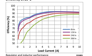
Efficiency at 25°C
Transient Response: 2A to 7A, at 5A/µs
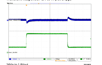
24Vin to 1.8Vout 331802 Cout = 6X 100µF Ceramic
Output Ripple: 24Vin, 1.8Vout at 10A
Short Circuit Test
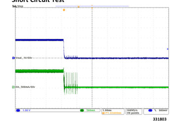
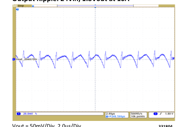
Vout = 50mV/Div, 2.0us/Div 331804 Cout = 6X 100µF Ceramic
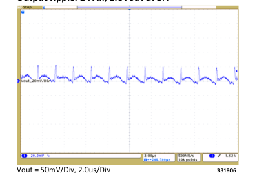
Output ripple: 24Vin, 1.8Vout at 5A
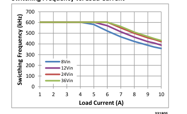
Switching Frequency vs. Load Current
331805
Cout = 6X 100µF Ceramic
800 735.6200 11/2012 Page 11 of 42
Page 12
PI3312-X0 (2.5 Vout) Electrical Characteristics
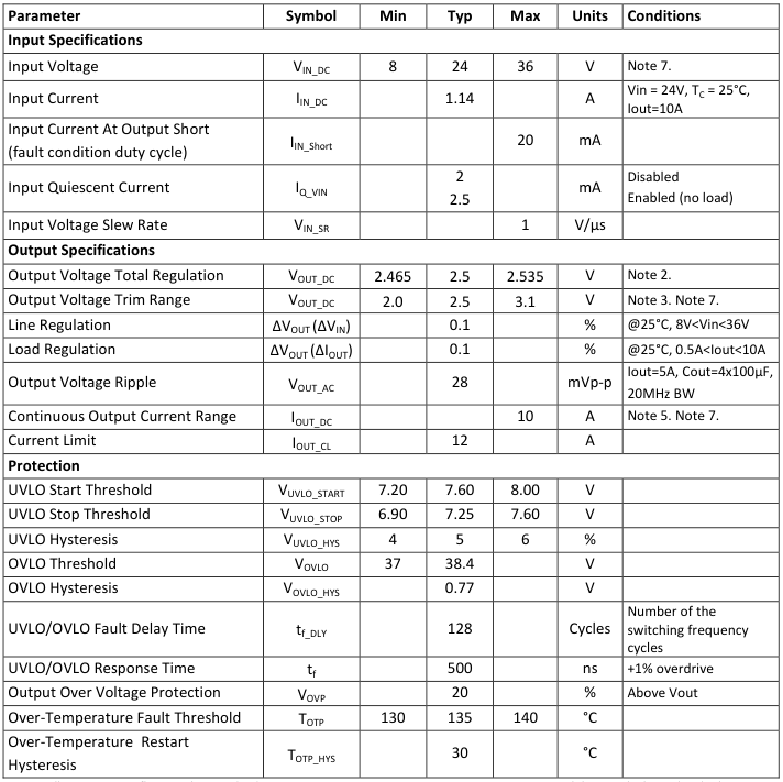
Specifications apply for -40C < TJ < 125C, Vin =24V, L1=200nH (Note 1) unless other conditions are noted.
Note 1: All parameters reflect regulator and inductor system performance. Measurements were made using a standard PI33XX evaluation board with 3x4” dimensions and 4 layer, 2oz copper. Refer to inductor pairing table within Application Description section for specific inductor manufacturer and value. Note 2: Regulator is assured to meet performance specifications by design, test correlation, characterization, and/or statistical process control.
Note 3: Output current capability may be limited and other performance may vary from noted electrical characteristics when switching frequency or Vout is modified. Note 4: Refer to Output Ripple plots. Note 5: Refer to Load Current vs. Ambient Temperature curves. Note 6: Refer to Switching Frequency vs. Load current curves. Note 7: Minimum 5V between Vin-Vout must be maintained or a minimum load of 1mA required.
800 735.6200 11/2012 Page 12 of 42
Page 13
PI3312-X0 (2.5 Vout) Electrical Characteristics
Specifications apply for -40C < TJ < 125C, Vin =24V, L1=200nH (Note 1) unless other conditions are noted.
| Parameter | Symbol | Min | Typ | Max | Units | Conditions | |
|---|---|---|---|---|---|---|---|
| Timing | |||||||
| Switching Frequency | f S | 500 | kHz | Note 6. | |||
| Fault Restart Delay | t FR_DLY | 30 | ms | ||||
| Sync In (SYNCI) | |||||||
| Synchronization Frequency Range | ∆f SYNCI | 50 | 110 | % | Relative to set switching frequency. Note 3. | ||
| SYNCI Threshold | V SYNCI | 2.5 | V | ||||
| Sync Out (SYNCO) | |||||||
| SYNCO High | V SYNCO_HI | 4.5 | V | Source 1mA | |||
| SYNCO Low | V SYNCO_LO | 0.5 | V | Sink 1mA | |||
| SYNCO Rise Time | t SYNCO_RT | 10 | 20 | ns | 20pF load | ||
| SYNCO Fall Time | t SYNCO_FT | 10 | 20 | ns | 20pF load | ||
| Soft Start And Tracking | |||||||
| TRK Active Range (Nominal) | V TRK | 0 | 1 | V | |||
| TRK Enable Threshold | V TRK_OV | 20 | 40 | 60 | mV | ||
| Charge Current (Soft – Start) | I TRK | -70 | -50 | -30 | µA | ||
| Discharge Current (Fault) | I TRK_DIS | 6.8 | mA | ||||
| Soft-Start Time | t SS | 2.2 | 2.6 | ms | C = 0 TRK | ||
| Enable | |||||||
| High Threshold | V EN_HI | 0.9 | 1 | 1.1 | V | ||
| Low Threshold | V EN_LO | 0.7 | 0.8 | 0.9 | V | ||
| Threshold Hysteresis | V EN_HYS | 100 | 200 | 300 | mV | ||
| Enable Pull-Up Voltage (floating, unfaulted) | V EN_PU | 2 | V | ||||
| Enable Pull-Down Voltage (floating, faulted) | V EN_PD | 0 | V | ||||
| Source Current | I EN_SO | -50 | uA | ||||
| Sink Current | I EN_SK | 50 | uA | ||||
Note 1: All parameters reflect regulator and inductor system performance. Measurements were made using a standard PI33XX evaluation board with 3x4” dimensions and 4 layer, 2oz copper. Refer to inductor pairing table within Application Description section for specific inductor manufacturer and value. Note 2: Regulator is assured to meet performance specifications by design, test correlation, characterization, and/or statistical process control.
Note 3: Output current capability may be limited and other performance may vary from noted electrical characteristics when switching frequency or Vout is modified. Note 4: Refer to Output Ripple plots. Note 5: Refer to Load Current vs. Ambient Temperature curves. Note 6: Refer to Switching Frequency vs. Load current curves. Note 7: Minimum 5V between Vin-Vout must be maintained or a minimum load of 1mA required.
800 735.6200 11/2012 Page 13 of 42
Page 14
PI3312-X0 (2.5 Vout) Electrical Characteristics
Efficiency at 25°C
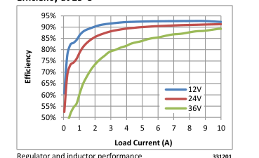
Regulator and inductor performance 331201
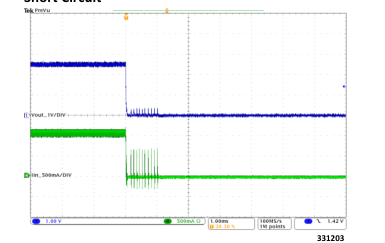
Short Circuit
Switching Frequency vs. Load Current
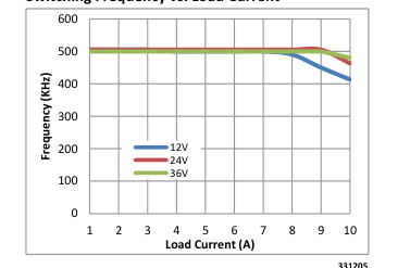
331205
Transient Response: 5A to 10A, at 5A/µs
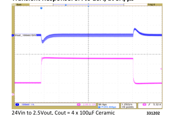
Vout (Ch1) = 100mV/Div, Iout (Ch4) = 2A/Div, 80us/Div
Output Ripple: 24Vin, 2.5Vout at 10A
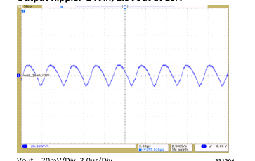
Vout = 20mV/Div, 2.0us/Div 331204 Cout = 4 x 100µF Ceramic
Output Ripple: 24Vin, 2.5Vout at 5A
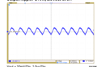
Vout = 20mV/Div, 2.0us/Div 331206 Cout = 4 x 100µF Ceramic
800 735.6200 11/2012 Page 14 of 42
Page 15
PI3312-X0 (2.5 Vout) Electrical Characteristics
Load Current vs. Ambient Temperature, 0 LFM
Load Current vs. Ambient Temperature, 200 LFM
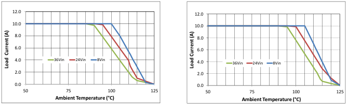
Regulator and inductor performance 331208
Regulator and inductor performance 331207
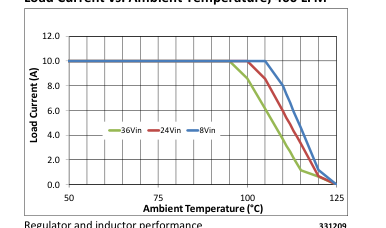
Load Current vs. Ambient Temperature, 400 LFM
800 735.6200 11/2012 Page 15 of 42
Page 16
PI3301-X0 (3.3 Vout) Electrical Characteristics
Specifications apply for -40C < TJ < 125C, Vin =24V, L1=200nH (Note 1) unless other conditions are noted.
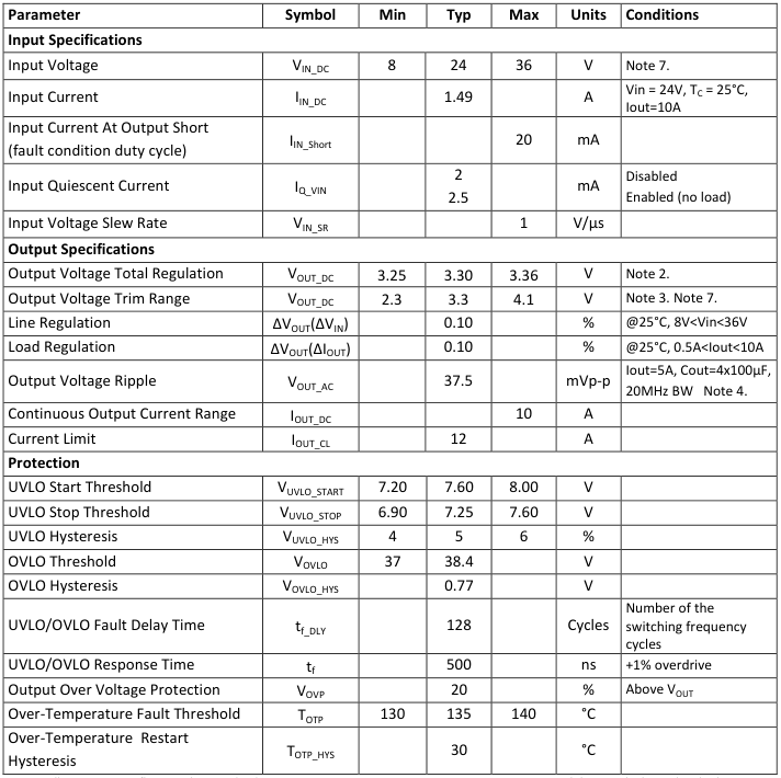
Note 1: All parameters reflect regulator and inductor system performance. Measurements were made using a standard PI33XX evaluation board with 3x4” dimensions and 4 layer, 2oz copper. Refer to inductor pairing table within Application Description section for specific inductor manufacturer and value. Note 2: Regulator is assured to meet performance specifications by design, test correlation, characterization, and/or statistical process control.
Note 3: Output current capability may be limited and other performance may vary from noted electrical characteristics when switching frequency or Vout is modified. Note 4: Refer to Output Ripple plots. Note 5: Refer to Load Current vs. Ambient Temperature curves. Note 6: Refer to Switching Frequency vs. Load current curves. Note 7: Minimum 5V between Vin-Vout must be maintained or a minimum load of 1mA required.
.
800 735.6200 11/2012 Page 16 of 42
Page 17
PI3301-X0 (3.3 Vout) Electrical Characteristics
Specifications apply for -40C < TJ < 125C, Vin =24V, L1=200nH (Note 1) unless other conditions are noted.
| Parameter | Symbol | Min | Typ | Max | Units | Conditions |
|---|---|---|---|---|---|---|
| Timing | ||||||
| Switching Frequency | f S | 650 | kHz | Note 6. | ||
| Fault Restart Delay | t FR_DLY | 30 | ms | |||
| Sync In (SYNCI) | ||||||
| Synchronization Frequency Range | ∆f SYNCI | 50 | 110 | % | Relative to set switching frequency. Note 3. | |
| SYNCI Threshold | V SYNCI | 2.5 | V | |||
| Sync Out (SYNCO) | ||||||
| SYNCO High | V SYNCO_HI | 4.5 | V | Source 1mA | ||
| SYNCO Low | V SYNCO_LO | 0.5 | V | Sink 1mA | ||
| SYNCO Rise Time | t SYNCO_RT | 10 | 20 | ns | 20pF load | |
| SYNCO Fall Time | t SYNCO_FT | 10 | 20 | ns | 20pF load | |
| Soft Start And Tracking | ||||||
| TRK Active Range (Nominal) | V TRK | 0 | 1 | V | ||
| TRK Enable Threshold | V TRK_OV | 20 | 40 | 60 | mV | |
| Charge Current (Soft – Start) | I TRK | -70 | -50 | -30 | µA | |
| Discharge Current (Fault) | I TRK_DIS | 6.8 | mA | |||
| Soft-Start Time | t SS | 2.2 | 2.6 | ms | C = 0 TRK | |
| Enable | ||||||
| High Threshold | V EN_HI | 0.9 | 1 | 1.1 | V | |
| Low Threshold | V EN_LO | 0.7 | 0.8 | 0.9 | V | |
| Threshold Hysteresis | V EN_HYS | 100 | 200 | 300 | mV | |
| Enable Pull-Up Voltage (floating, unfaulted) | V EN_PU | 2 | V | |||
| Enable Pull-Down Voltage (floating, faulted) | V EN_PD | 0 | V | |||
| Source Current | I EN_SO | -50 | uA | |||
| Sink Current | I EN_SK | 50 | uA | |||
Note 1: All parameters reflect regulator and inductor system performance. Measurements were made using a standard PI33XX evaluation board with 3x4” dimensions and 4 layer, 2oz copper. Refer to inductor pairing table within Application Description section for specific inductor manufacturer and value. Note 2: Regulator is assured to meet performance specifications by design, test correlation, characterization, and/or statistical process control.
Note 3: Output current capability may be limited and other performance may vary from noted electrical characteristics when switching frequency or Vout is modified. Note 4: Refer to Output Ripple plots. Note 5: Refer to Load Current vs. Ambient Temperature curves. Note 6: Refer to Switching Frequency vs. Load current curves. Note 7: Minimum 5V between Vin-Vout must be maintained or a minimum load of 1mA required.
800 735.6200 11/2012 Page 17 of 42
Page 18
PI3301-X0 (3.3 Vout) Electrical Characteristics
Transient Response: 2A to 7A, at 5A/µs
Efficiency at 25°C
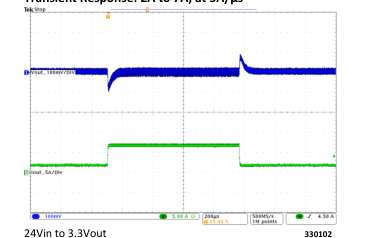
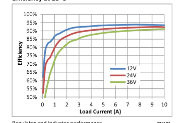
Regulator and inductor performance 330101
Short Circuit
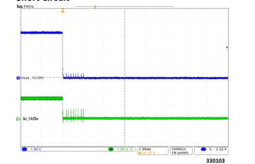
Switching Frequency vs. Load Current
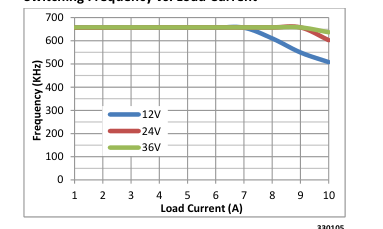
330105
Cout = 4 x 100µF Ceramic
Output Ripple: 24Vin, 3.3Vout at 10A
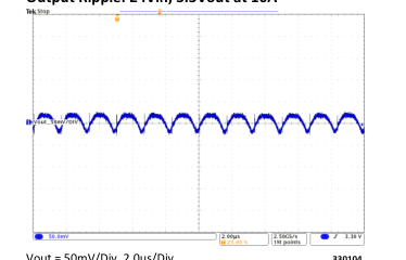
Vout = 50mV/Div, 2.0us/Div 330104 Cout = 4 x 100µF Ceramic
Output Ripple: 24Vin, 3.3Vout at 5A
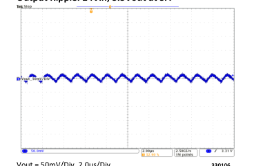
Vout = 50mV/Div, 2.0us/Div 330106 Cout = 4 x 100µF Ceramic
800 735.6200 11/2012 Page 18 of 42
Page 19
PI3301-X0 (3.3 Vout) Electrical Characteristics
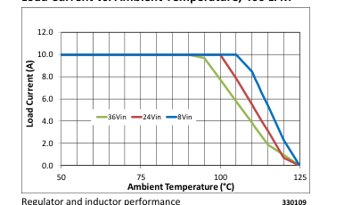
Load Current vs. Ambient Temperature, 0 LFM
Load Current vs. Ambient Temperature, 200 LFM
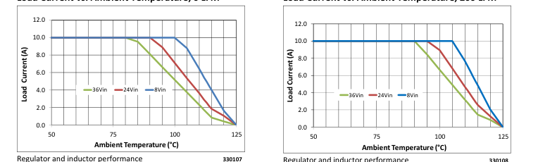
Regulator and inductor performance 330108
Load Current vs. Ambient Temperature, 400 LFM
800 735.6200 11/2012 Page 19 of 42
Page 20
PI3302-X0 (5.0 Vout) Electrical Characteristics
Specifications apply for -40C < TJ < 125C, Vin =24V, L1=200nH (Note 1) unless other conditions are noted.
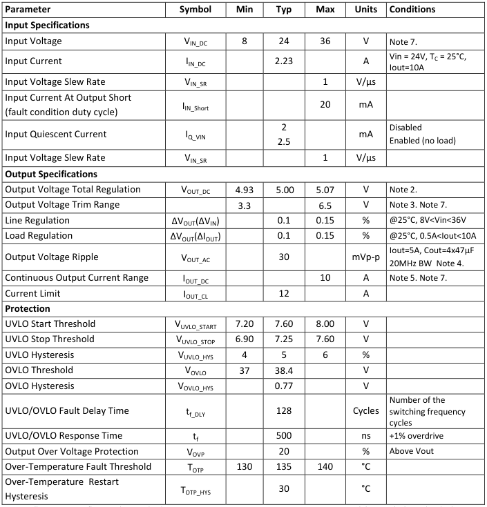
Note 1: All parameters reflect regulator and inductor system performance. Measurements were made using a standard PI33XX evaluation board with 3x4” dimensions and 4 layer, 2oz copper. Refer to inductor pairing table within Application Description section for specific inductor manufacturer and value. Note 2: Regulator is assured to meet performance specifications by design, test correlation, characterization, and/or statistical process control.
Note 3: Output current capability may be limited and other performance may vary from noted electrical characteristics when switching frequency or Vout is modified. Note 4: Refer to Output Ripple plots. Note 5: Refer to Load Current vs. Ambient Temperature curves. Note 6: Refer to Switching Frequency vs. Load current curves. Note 7: Minimum 5V between Vin-Vout must be maintained or a minimum load of 3mA required.
800 735.6200 11/2012 Page 20 of 42
Page 21
PI3302-X0 (5.0 Vout) Electrical Characteristics
Specifications apply for -40C < TJ < 125C, Vin =24V, L1=200nH (Note 1) unless other conditions are noted.
| Parameter | Symbol | Min | Typ | Max | Units | Conditions |
|---|---|---|---|---|---|---|
| Timing | ||||||
| Switching Frequency | f S | 1.0 | MHz | Note 6. | ||
| Fault Restart Delay | t FR_DLY | 30 | ms | |||
| Sync In (SYNCI) | ||||||
| Synchronization Frequency Range | ∆f SYNCI | 50 | 110 | % | Relative to set switching frequency. Note 3. | |
| SYNCI Threshold | V SYNCI | 2.5 | V | |||
| Sync Out (SYNCO) | ||||||
| SYNCO High | V SYNCO_HI | 4.5 | V | Source 1mA | ||
| SYNCO Low | V SYNCO_LO | 0.5 | V | Sink 1mA | ||
| SYNCO Rise Time | t SYNCO_RT | 10 | 20 | ns | 20pF load | |
| SYNCO Fall Time | t SYNCO_FT | 10 | 20 | ns | 20pF load | |
| Soft Start And Tracking | ||||||
| TRK Active Range (Nominal) | V TRK | 0 | 1 | V | ||
| TRK Enable Threshold | V TRK_OV | 20 | 40 | 60 | mV | |
| Charge Current (Soft – Start) | I TRK | -70 | -50 | -30 | µA | |
| Discharge Current (Fault) | I TRK_DIS | 6.8 | mA | |||
| Soft-Start Time | t SS | 2.2 | 2.6 | ms | C = 0 TRK | |
| Enable | ||||||
| High Threshold | V EN_HI | 0.9 | 1 | 1.1 | V | |
| Low Threshold | V EN_LO | 0.7 | 0.8 | 0.9 | V | |
| Threshold Hysteresis | V EN_HYS | 100 | 200 | 300 | mV | |
| Enable Pull-Up Voltage (floating, unfaulted) | V EN_PU | 2 | V | |||
| Enable Pull-Down Voltage (floating, faulted) | V EN_PD | 0 | V | |||
| Source Current | I EN_SO | -50 | uA | |||
| Sink Current | I EN_SK | 50 | uA | |||
Note 1: All parameters reflect regulator and inductor system performance. Measurements were made using a standard PI33XX evaluation board with 3x4” dimensions and 4 layer, 2oz copper. Refer to inductor pairing table within Application Description section for specific inductor manufacturer and value. Note 2: Regulator is assured to meet performance specifications by design, test correlation, characterization, and/or statistical process control.
Note 3: Output current capability may be limited and other performance may vary from noted electrical characteristics when switching frequency or Vout is modified. Note 4: Refer to Output Ripple plots. Note 5: Refer to Load Current vs. Ambient Temperature curves. Note 6: Refer to Switching Frequency vs. Load current curves. Note 7: Minimum 5V between Vin-Vout must be maintained or a minimum load of 3mA required.
800 735.6200 11/2012 Page 21 of 42
Page 22
PI3302-X0 (5.0 Vout) Electrical Characteristics
Efficiency at 25°C
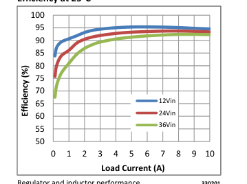
Regulator and inductor performance 330201
Short Circuit Test
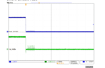
Switching Frequency vs. Load Current
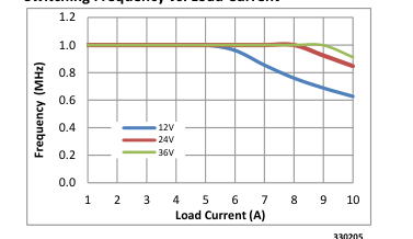
330205
Transient Response: 2A to 7A, at 5A/µs
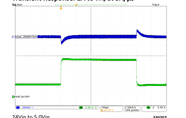
24Vin to 5.0Vin 330202 Cout = 4 X 47uF Ceramic
Output Ripple: 24Vin, 5.0Vout at 10A
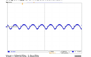
Cout = 4 x 47µF Ceramic
Output Ripple: 24Vin, 5.0Vout at 5A
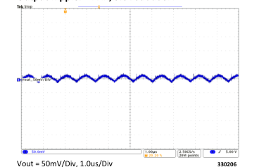
Cout = 4 X 47uF Ceramic
800 735.6200 11/2012 Page 22 of 42
Page 23
PI3302-X0 (5.0 Vout) Electrical Characteristics
Load Current vs. Ambient Temperature, 0 LFM
Load Current vs. Ambient Temperature, 200 LFM
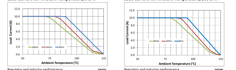
Regulator and inductor performance 330207
Regulator and inductor performance 330208
Load Current vs. Ambient Temperature, 400 LFM
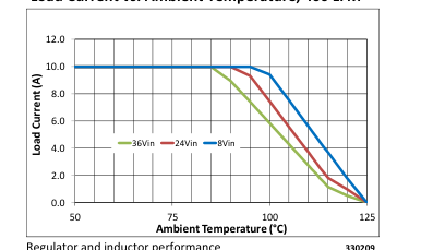
Regulator and inductor performance 330209
800 735.6200 11/2012 Page 23 of 42
Page 24
PI3303-X0 (12.0 Vout) Electrical Characteristics
Specifications apply for -40C < TJ < 125C, Vin =24V, L1=230nH (Note 1) unless other conditions are noted.
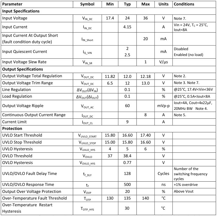
Note 1: All parameters reflect regulator and inductor system performance. Measurements were made using a standard PI33XX evaluation board with 3x4” dimensions and 4 layer, 2oz copper. Refer to inductor pairing table within Application Description section for specific inductor manufacturer and value. Note 2: Regulator is assured to meet performance specifications by design, test correlation, characterization, and/or statistical process control.
Note 3: Output current capability may be limited and other performance may vary from noted electrical characteristics when switching frequency or Vout is modified. Note 4: Refer to Output Ripple plots. Note 5: Refer to Load Current vs. Ambient Temperature curves. Note 6: Refer to Switching Frequency vs. Load current curves. Note 7: Minimum 5V between Vin-Vout must be maintained or a minimum load of 1mA required.
800 735.6200 11/2012 Page 24 of 42
Page 25
PI3303-X0 (12.0 Vout) Electrical Characteristics
Specifications apply for -40C < TJ < 125C, Vin =24V, L1=230nH (Note 1) unless other conditions are noted.
| Parameter | Symbol | Min | Typ | Max | Units | Conditions |
|---|---|---|---|---|---|---|
| Timing | ||||||
| Switching Frequency | f S | 1.4 | MHz | Note 6. | ||
| Fault Restart Delay | t FR_DLY | 30 | ms | |||
| Sync In (SYNCI) | ||||||
| Synchronization Frequency Range | ∆f SYNCI | 50 | 110 | % | Relative to set switching frequency. Note 3. | |
| SYNCI Threshold | V SYNCI | 2.5 | V | |||
| Sync Out (SYNCO) | ||||||
| SYNCO High | V SYNCO_HI | 4.5 | V | Source 1mA | ||
| SYNCO Low | V SYNCO_LO | 0.5 | V | Sink 1mA | ||
| SYNCO Rise Time | t SYNCO_RT | 10 | 20 | ns | 20pF load | |
| SYNCO Fall Time | t SYNCO_FT | 10 | 20 | ns | 20pF load | |
| Soft Start And Tracking | ||||||
| TRK Active Range (Nominal) | V TRK | 0 | 1 | V | ||
| TRK Enable Threshold | V TRK_OV | 20 | 40 | 60 | mV | |
| Charge Current (Soft – Start) | I TRK | -70 | -50 | -30 | µA | |
| Discharge Current (Fault) | I TRK_DIS | 6.8 | mA | |||
| Soft-Start Time | t SS | 2.2 | 2.6 | ms | C = 0 TRK | |
| Enable | ||||||
| High Threshold | V EN_HI | 0.9 | 1 | 1.1 | V | |
| Low Threshold | V EN_LO | 0.7 | 0.8 | 0.9 | V | |
| Threshold Hysteresis | V EN_HYS | 100 | 200 | 300 | mV | |
| Enable Pull-Up Voltage (floating, unfaulted) | V EN_PU | 2 | V | |||
| Enable Pull-Down Voltage (floating, faulted) | V EN_PD | 0 | V | |||
| Source Current | I EN_SO | -50 | uA | |||
| Sink Current | I EN_SK | 50 | uA | |||
Note 1: All parameters reflect regulator and inductor system performance. Measurements were made using a standard PI33XX evaluation board with 3x4” dimensions and 4 layer, 2oz copper. Refer to inductor pairing table within Application Description section for specific inductor manufacturer and value. Note 2: Regulator is assured to meet performance specifications by design, test correlation, characterization, and/or statistical process control.
Note 3: Output current capability may be limited and other performance may vary from noted electrical characteristics when switching frequency or Vout is modified. Note 4: Refer to Output Ripple plots. Note 5: Refer to Load Current vs. Ambient Temperature curves. Note 6: Refer to Switching Frequency vs. Load current curves. Note 7: Minimum 5V between Vin-Vout must be maintained or a minimum load of 1mA required.
800 735.6200 11/2012 Page 25 of 42
Page 26
PI3303-X0 (12.0 Vout) Electrical Characteristics
Efficiency at 25°
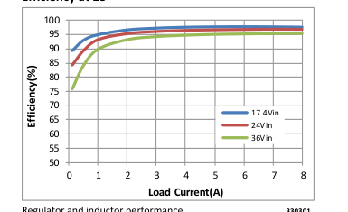
Regulator and inductor performance 330301
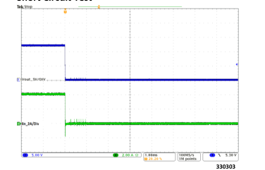
Short Circuit Test
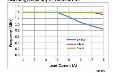
Switching Frequency vs. Load Current
Transient Response: 4A to 8A, at 5A/µs
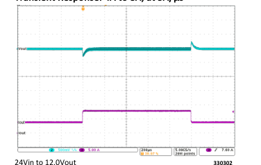
Cout = 4 X 22uF Ceramic
Output Ripple: Vin = 24V, Vout = 12V at 8A
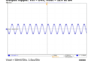
Cout = 4 X 22uF Ceramic
Output Ripple: Vin = 24V, Vout = 12V at 4A
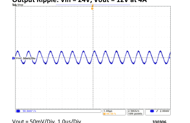
Vout = 50mV/Div, 1.0us/Div 330306 Cout = 4 X 22uF Ceramic
800 735.6200 11/2012 Page 26 of 42
Page 27
PI3303-X0 (12.0 Vout) Electrical Characteristics
Load Current vs. Ambient Temperature, 0 LFM
Load Current vs. Ambient Temperature, 200 LFM
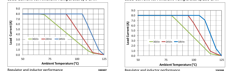
Regulator and inductor performance 330308
Load Current vs. Ambient Temperature, 400 LFM
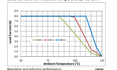
Regulator and inductor performance 330309
800 735.6200 11/2012 Page 27 of 42
Page 28
PI3305-X0 (15.0 Vout) Electrical Characteristics
Specifications apply for -40C < TJ < 125C, Vin =24V, L1=230nH (Note 1) unless other conditions are noted.
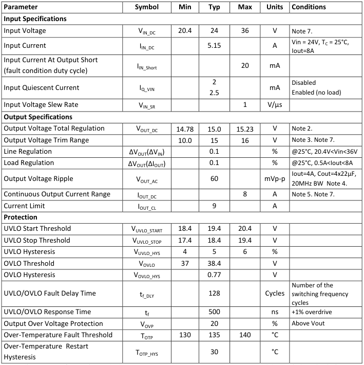
Note 1: All parameters reflect regulator and inductor system performance. Measurements were made using a standard PI33XX evaluation board with 3x4” dimensions and 4 layer, 2oz copper. Refer to inductor pairing table within Application Description section for specific inductor manufacturer and value. Note 2: Regulator is assured to meet performance specifications by design, test correlation, characterization, and/or statistical process control.
Note 3: Output current capability may be limited and other performance may vary from noted electrical characteristics when switching frequency or Vout is modified. Note 4: Refer to Output Ripple plots. Note 5: Refer to Load Current vs. Ambient Temperature curves. Note 6: Refer to Switching Frequency vs. Load current curves. Note 7: Minimum 5V between Vin-Vout must be maintained or a minimum load of 1mA required.
800 735.6200 11/2012 Page 28 of 42
Page 29
PI3305-X0 (15.0 Vout) Electrical Characteristics
Specifications apply for -40C < TJ < 125C, Vin =24V, L1=230nH (Note 1) unless other conditions are noted.
| Parameter | Symbol | Min | Typ | Max | Units | Conditions |
|---|---|---|---|---|---|---|
| Timing | ||||||
| Switching Frequency | f S | 1.5 | MHz | Note 6. | ||
| Fault Restart Delay | t FR_DLY | 30 | ms | |||
| Sync In (SYNCI) | ||||||
| Synchronization Frequency Range | ∆f SYNCI | 50 | 110 | % | Relative to set switching frequency. Note 3. | |
| SYNCI Threshold | V SYNCI | 2.5 | V | |||
| Sync Out (SYNCO) | ||||||
| SYNCO High | V SYNCO_HI | 4.5 | V | Source 1mA | ||
| SYNCO Low | V SYNCO_LO | 0.5 | V | Sink 1mA | ||
| SYNCO Rise Time | t SYNCO_RT | 10 | 20 | ns | 20pF load | |
| SYNCO Fall Time | t SYNCO_FT | 10 | 20 | ns | 20pF load | |
| Soft Start And Tracking | ||||||
| TRK Active Range (Nominal) | V TRK | 0 | 1 | V | ||
| TRK Enable Threshold | V TRK_OV | 20 | 40 | 60 | mV | |
| Charge Current (Soft – Start) | I TRK | -70 | -50 | -30 | µA | |
| Discharge Current (Fault) | I TRK_DIS | 6.8 | mA | |||
| Soft-Start Time | t SS | 2.2 | 2.6 | ms | C = 0 TRK | |
| Enable | ||||||
| High Threshold | V EN_HI | 0.9 | 1 | 1.1 | V | |
| Low Threshold | V EN_LO | 0.7 | 0.8 | 0.9 | V | |
| Threshold Hysteresis | V EN_HYS | 100 | 200 | 300 | mV | |
| Enable Pull-Up Voltage (floating, unfaulted) | V EN_PU | 2 | V | |||
| Enable Pull-Down Voltage (floating, faulted) | V EN_PD | 0 | V | |||
| Source Current | I EN_SO | -50 | uA | |||
| Sink Current | I EN_SK | 50 | uA | |||
Note 1: All parameters reflect regulator and inductor system performance. Measurements were made using a standard PI33XX evaluation board with 3x4” dimensions and 4 layer, 2oz copper. Refer to inductor pairing table within Application Description section for specific inductor manufacturer and value. Note 2: Regulator is assured to meet performance specifications by design, test correlation, characterization, and/or statistical process control.
Note 3: Output current capability may be limited and other performance may vary from noted electrical characteristics when switching frequency or Vout is modified. Note 4: Refer to Output Ripple plots. Note 5: Refer to Load Current vs. Ambient Temperature curves. Note 6: Refer to Switching Frequency vs. Load current curves. Note 7: Minimum 5V between Vin-Vout must be maintained or a minimum load of 1mA required.
800 735.6200 11/2012 Page 29 of 42
Page 30
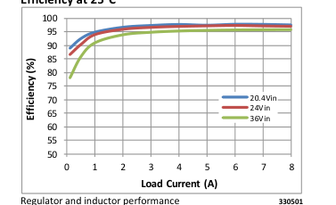
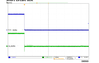
PI3305-X0 (15 Vout) Electrical Characteristics
Efficiency at 25°C
Transient Response: 2A to 6A, at 5A/µs
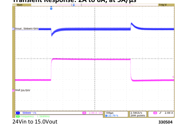
Cout = 4x22µF Ceramic
Short circuit test
Output Ripple: 24Vin, 15Vout at 8A
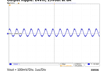
Cout = 4x22µF Ceramic
Output Ripple: 24Vin, 15Vout at 4A
Switching Frequency vs. Load Current
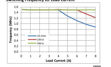
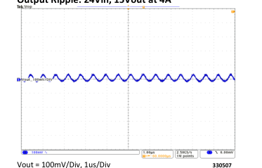
330505
Cout = 4x22µF Ceramic
800 735.6200 11/2012 Page 30 of 42
Page 31
PI3305-X0 (15 Vout) Electrical Characteristics
Load Current vs. Ambient Temperature, 0 LFM
Load Current vs. Ambient Temperature, 200 LFM
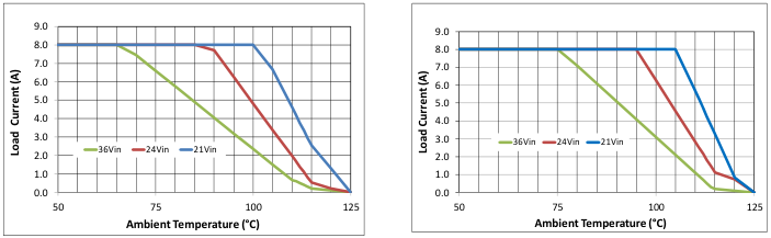
Regulator and inductor performance 330508
Regulator and inductor performance 330507
Load Current vs. Ambient Temperature, 400 LFM
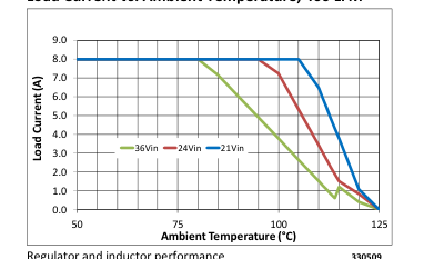
Regulator and inductor performance 330509
800 735.6200 11/2012 Page 31 of 42
Page 32
Functional Description
The PI33XX is a family of highly integrated ZVS-Buck regulators. The PI33XX has a set output voltage that is trimmable within a prescribed range shown in Table 1. Performance and maximum output current are characterized with a specific external power inductor (see Table 5).
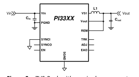
Figure 2 - ZVS-Buck with required components
For basic operation, Figure 2 shows the connections and components required. No additional design or settings are required.
ENABLE (EN)
EN is the enable pin of the converter. The EN Pin is referenced to SGND and permits the user to turn the converter on or off. The EN default polarity is a positive logic assertion. If the EN pin is left floating or asserted high, the converter output is enabled. Pulling EN pin below 0.8 Vdc with respect to SGND will disable the regulator output.
The EN input polarity can be programmed (PI33XX-20 and PI33XX-21 versions only) via the I2C data bus. When the EN pin polarity is programmed for negative logic assertion; and if the EN pin is left floating, the regulator output is enabled. Pulling the EN pin above 1.0 Vdc with respect to SGND, will disable the regulator output.
Switching Frequency Synchronization The SYNCI input allows the user to synchronize the controller switching frequency by an external clock referenced to SGND. The external clock can synchronize the unit between 50% and 110% of the preset switching frequency (fS). For PI33XX-20 and PI33XX-21 versions only, the phase delay can be programmed via I2C bus with respect to the clock
applied at SYNCI pin. Phase delay allows PI33XX regulators to be paralleled and operate in an interleaving mode.
The PI33XX default for SYNCI is to sync with respect to the falling edge of the applied clock providing 180° phase shift from SYNCO. This allows for the paralleling of two PI33XX devices without the need for further user programming or external sync clock circuitry. The user can change the SYNCI polarity to sync with the external clock rising edge via the I2C data bus (PI33XX-20 and PI33XX-21 versions only).
When using the internal oscillator, the SYNCO pin provides a 5V clock that can be used to sync other regulators. Therefore, one PI33XX can act as the lead regulator and have additional PI33XXs running in parallel and interleaved.
Output Voltage Trim The PI33XX output voltage can be trimmed up from the preset output by connecting a resistor from ADJ pin to SGND and can be trimmed down by connecting a resistor from ADJ pin to VOUT. The Table 2 defines the voltage ranges for the PI33XX family.
| Device | Output Voltage | |
| Set | Range | |
| PI3311-X0-LGIZ | 1.0V | 1.0 to 1.4V |
| PI3318-X0-LGIZ | 1.8V | 1.4 to 2.0V |
| PI3312-X0-LGIZ | 2.5V | 2.0 to 3.1V |
| PI3301-X0-LGIZ | 3.3V | 2.3 to 4.1V |
| PI3302-X0-LGIZ | 5.0V | 3.3 to 6.5V |
| PI3303-X0-LGIZ | 12V | 6.5 to 13.0V |
| PI3305-X0-LGIZ | 15V | 10.0 to 16.0V |
Table 2 - PI33XX family output voltage ranges.
Soft-Start The PI33XX includes an internal soft-start capacitor to ramp the output voltage in 2ms from 0V to full output voltage. Connecting an external capacitor from the TRK pin to SGND will increase the start-up ramp period. See, “Soft Start Adjustment and Track,”
800 735.6200 11/2012 Page 32 of 42
Page 33
in the Applications Description section for more details. Remote Sensing An internal 100Ω resistor is connected between REM pin and VOUT pin to provide regulation when the REM is left open. With REM open, the converter will regulate 100mV above its set point. Connect REM to the desired reference node to be regulated.
Output Current Limit Protection PI33XX has two methods implemented to protect from output short or over current condition.
Slow Current Limit protection: prevents the output load from sourcing current higher than the regulator’s maximum rated current. If the output current exceeds the Current Limit (IOUT_CL) for 1024us, a slow current limit fault is initiated and the regulator is shutdown which eliminates output current flow. After Fault Restart Delay (tFR_DLY), a soft-start cycle is initiated. This restart cycle will be repeated indefinitely until the excessive load is removed.
Fast Current Limit protection: PI33XX monitors the regulator inductor current pulse-by-pulse to prevent the output from supplying very high current due to a sudden low impedance short. If the regulator senses a high inductor current pulse, it will initiate a fault and stop switching until Fault Restart Delay ends and then initiate a soft-start cycle.
Both the Fast and Slow current limit faults are stored in a Fault Register and can be read and cleared (PI33XX-20 and PI33XX-21 versions only) via I2C data bus.
Input Under-Voltage Lockout If VIN falls below the input Under Voltage Lockout (UVLO) threshold, but remains high enough to power the internal bias supply, the PI33XX will complete the current cycle and stop switching. If VIN recovers within 128 switching cycles, the PI33XX will resume normal operation. If this time limit is exceeded, the system will enter a low power state and initiate a fault. The system will restart once the input voltage is reestablished and after the Fault Restart Delay. A UVLO fault is stored in a Fault Register and can be
read and cleared (PI33XX-20 and PI33XX-21 versions only) via I2C data bus.
Input Over Voltage Lockout If VIN exceeds the input Over Voltage Lockout (OVLO) threshold (VOVLO), while the controller is running, the PI33XX will complete the current cycle and stop switching. If VIN recovers within 128 switching cycles, the PI33XX will resume normal operation. Otherwise, the system will enter a low power state and sets an OVLO fault. The system will resume operation when the input voltage falls below 98% of the OVLO threshold and after the Fault Restart Delay. The OVLO fault is stored in a Fault Register and can be read and cleared (PI33XX-20 and PI33XX-21 versions only) via I2C data bus.
Output Over Voltage Protection The PI33XX family is equipped with output Over Voltage Protection (OVP) to prevent damage to input voltage sensitive devices. If the output voltage exceeds 20% of its set regulated value, the regulator will complete the current cycle, stop switching and issue an OVP fault. The system will resume operation once the output voltage falls below the OVP threshold and after Fault Restart Delay. The OVP fault is stored in a Fault Register and can be read and cleared (PI33XX-20 and PI33XX-21 versions only) via I2C data bus.
Over Temperature Protection The internal package temperature is monitored to prevent internal components from reaching their thermal maximum. If the Over Temperature Protection Threshold (OTP) is exceeded (TOTP), the regulator will complete the current switching cycle, enter a low power mode, set a fault flag, and will soft-start when the internal temperature falls below Over-Temperature Restart Hysteresis (TOTP_HYS). The OTP fault is stored in a Fault Register and can be read and cleared (PI33XX-20 and PI33XX-21 versions only) via I2C data bus.
Pulse Skip Mode (PSM) PI33XX features a PSM to achieve high efficiency at light loads. The regulators are setup to skip pulses if
800 735.6200 11/2012 Page 33 of 42
Page 34
EAO falls below a PSM threshold. Depending on conditions and component values, this may result in single pulses or several consecutive pulses followed by skipped pulses. Skipping cycles significantly reduces gate drive power and improves light load efficiency. The regulator will leave PSM once the EAO rises above the Skip Mode threshold.
Variable Frequency Operation Each PI33XX is preprogrammed to a base operating frequency, with respect to the power stage inductor (see Table 5), to operate at peak efficiency across line and load variations. At low line and high load applications, the base frequency will decrease to accommodate these extreme operating ranges. By stretching the frequency, the ZVS operation is preserved throughout the total input line voltage range therefore maintaining optimum efficiency.
Parallel Operation Paralleling multiple PI33XX modules can be used to increase the output current capability of a single power rail and reduce output voltage ripple.
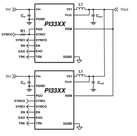
Figure 3 - PI33XX parallel operation
By connecting the EAO pins and SGND pins of each module together the units will share the current equally. When the TRK pins of each unit are connected together, the units will track each other during soft-start and all unit EN pins have to be released to allow the units to start (See Figure 3). Also, any fault event in any regulator will disable the
other regulators. The two regulators will be out of phase with each other reducing output ripple (refer to Switching Frequency Synchronization).
To provide synchronization between regulators over the entire operational frequency range, the Parallel Good (PGD) pin must be connected to the lead regulator’s SYNCI pin and a 2.5kΩ Resistor, R1, must be placed between SYNCO return and the lead regulator’s SYNCI pin, as shown in Figure 3. In this configuration, at system soft-start, the PGD pin pulls SYNCI low forcing the lead regulator to initialize the open-loop startup synchronization. Once the regulators reach regulation, SYNCI is released and the system is now synchronized in a closed-loop configuration which allows the system to adjust, on the fly, when any of the individual regulators begin to enter variable frequency mode in the loop.
Multi-phasing three regulators is possible (PI33XX-20 and PI33XX-21 only) with no change to the basic single-phase design. For more information about how to program phase delays within the regulator, please refer to Picor application note PI33XX-2X Multi-Phase Design Guide.
I2C Interface Operation PI33XX-20 and PI33XX-21 provide an I2C digital interface that enables the user to program the EN pin polarity (from high to low assertion) and switching frequency synchronization phase/delay. These are one time programmable options to the device.
Also, the PI33XX-20 and PI33XX-21 allow for dynamic Vout margining via I2C that is useful during development (settings stored in volatile memory only and not retained by the device). The PI33XX-20 and PI33XX-21 also have the option for fault telemetry including:
Over temperature protection Fast/Slow current limit Output voltage high Input overvoltage Input undervoltage
800 735.6200 11/2012 Page 34 of 42
Page 35
For more information about how to utilize the I2C interface please refer to Picor application note PI33XX-2X I2C Digital Interface Guide.
Application Description
Output Voltage Trim The PI33XX family of Buck Regulators provides seven common output voltages: 1.0V, 1.8V, 2.5V, 3.3V, 5.0V, 12V and 15V. A post-package trim step is implemented to offset any resistor divider network errors ensuring maximum output accuracy. With a single resistor connected from the ADJ pin to SGND or REM, each device’s output can be varied above or below the nominal set voltage (with the exception of the PI3311-X0 which can only be above the set voltage of 1V).
| Device | Output Voltage | |
| Set | Range | |
| PI3311-X0-LGIZ | 1.0V | 1.0 to 1.4V |
| PI3318-X0-LGIZ | 1.8V | 1.4 to 2.0V |
| PI3312-X0-LGIZ | 2.5V | 2.0 to 3.1V |
| PI3301-X0-LGIZ | 3.3V | 2.3 to 4.1V |
| PI3302-X0-LGIZ | 5.0V | 3.3 to 6.5V |
| PI3303-X0-LGIZ | 12V | 6.5 to 13.0V |
| PI3305-X0-LGIZ | 15V | 10.0 to 16.0V |
Table 3 - PI33XX family output voltage ranges
The remote pin (REM) should always be connected to the VOUT pin, if not used, to prevent an output voltage offset. Figure 4 shows the internal feedback voltage divider network.
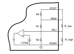
Figure 4 - Internal resistor divider network
R1, R2, and R4 are all internal 1.0 % resistors and R_low and R_high are external resistors for which the designer can add to modify VOUT to a desired output. The internal resistor value for each regulator is listed below in Table 4.
| Device | R1 | R2 | R4 |
| PI3311-X0-LGIZ | 1k | Open | 100 |
| PI3318-X0-LGIZ | 0.806K | 1.0k | 100 |
| PI3312-X0-LGIZ | 1.5k | 1.0k | 100 |
| PI3301-X0-LGIZ | 2.61k | 1.13k | 100 |
| PI3302-X0-LGIZ | 4.53k | 1.13k | 100 |
| PI3303-X0-LGIZ | 11.0k | 1.0k | 100 |
| PI3305-X0-LGIZ | 14.0k | 1.0k | 100 |
Table 4 - PI33XX Internal divider values
By choosing an output voltage value within the ranges stated in Table 3, VOUT can simply be adjusted up or down by selecting the proper R_high or R_low value, respectively. The following equations can be used to calculate R_high and R_low values:
( )
( ) ( )
( )
( ) (
)
If, for example, a 4.0V output is needed, the user should choose the regulator with a trim range covering 4.0V from Table 3. For this example, the PI3301 is selected (3.3V set voltage). First step would be to use Equation (1) to calculate R_high since the required output voltage is higher than the regulator set voltage. The resistor-divider network values for the PI3301 are can be found in Table 4 and are R1=2.61kΩ and R2=1.13kΩ. Inserting these values in to Equation (1), R_high is calculated as follows:
( ) ( )
800 735.6200 11/2012 Page 35 of 42
Page 36
Resistor R-high would be connected as in Figure 4 to achieve the 4.0V regulator output. No R_low resistor would be used since in this example the trim is above the regulator set voltage.
Soft-Start Adjust and Tracking The TRK pin offers a means to increase the regulator’s soft-start time or to track with additional regulators. The soft-start slope is controlled by an internal 100nF and a fixed charge current to provide a minimum startup time of 2ms (typical) for all PI33XX regulators. By adding an additional external capacitor to the TRK pin, the soft-start time can be increased further. The following equation can be used to calculate the proper capacitor for a desired soft-start times:
( )
Where, tTRK is the soft-start time and ITRK is a 50uA internal charge current (see Electrical Characteristics for limits).
There is typically either proportional or direct tracking implemented within a design. For proportional tracking between several regulators at startup, simply connect all devices TRK pins together. This type of tracking will force all connected regulators to startup and reach regulation at the same time (see Figure 5 (a)).
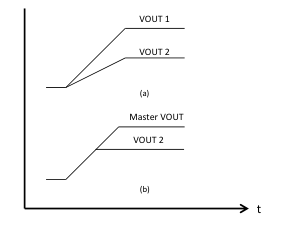
Figure 5 - PI33XX tracking methods
For Direct Tracking, choose the regulator with the highest output voltage as the master and connect the master to the TRK pin of the other regulators
through a divider (Figure 6) with the same ratio as the slave’s feedback divider (see Table 4 for values).
Master VOUT
R1
PI33XX
TRK Slave
R2
SGND
Figure 6 - Voltage divider connections for direct tracking
All connected regulators’ soft-start slopes will track with this method. Direct tracking timing is demonstrated in Figure 5 (b). All tracking regulators should have their Enable (EN) pins connected together to work properly.
Inductor Pairing The PI33XX utilizes an external inductor. This inductor has been optimized for maximum efficiency performance. Table 5 details the specific inductor value and part number utilized for each PI33XX device and are manufactured by either Picor or Cooper Bussman Coiltronics accordingly.
| Device | Inductor [nH] | Inductor Part Number | Manufacturer |
|---|---|---|---|
| PI3311-X0 | 125 | PI6125-00-FPIZ | Picor |
| PI3318-X0 | 155 | PI6155-00-FPIZ | Picor |
| PI3312-X0 | 200 | FPT705-200-R | Coiltronics |
| PI3301-X0 | 200 | FPT705-200-R | Coiltronics |
| PI3302-X0 | 200 | FPT705-200-R | Coiltronics |
| PI3303-X0 | 230 | FPT705-230-R | Coiltronics |
| PI3305-X0 | 230 | FPT705-230-R | Coiltronics |
Table 5 - PI33XX Inductor pairing
Thermal Derating Thermal de-rating curves are provided that are based on component temperature changes versus load current, input voltage and air flow. It is recommended to use these curves as a guideline for proper thermal de-rating. These curves represent the entire system and are inclusive to both the Picor regulator and the external inductor. Maximum
800 735.6200 11/2012 Page 36 of 42
Page 37
thermal operation is limited by either the MOSFETs or inductor depending upon line and load conditions.
Thermal measurements were made using a standard PI33XX Evaluation board which is 3x4 inches in area and uses 4-layer, 2oz copper. Thermal measurements were made on the three main power devices, the two internal MOSFETs and the external inductor, with air flows of 0, 200, and 400 LFM.
800 735.6200 11/2012 Page 37 of 42
Page 38
Filter Considerations The PI33XX requires input bulk storage capacitance as well as low impedance ceramic X5R input capacitors to ensure proper start up and high frequency decoupling for the power stage. The PI33XX will draw nearly all of the high frequency current from the low impedance ceramic capacitors when the main high side MOSFET is conducting. During the time the high side MOSFET is off, they are replenished from the bulk capacitor. If the input impedance is high at the switching frequency of the converter, the bulk capacitor must supply all of the average current into the converter, including replenishing the ceramic capacitors. This value has been chosen to be 100µF so that the PI33XX can
start up into a full resistive load and supply the output capacitive load with the default minimum soft start capacitor when the input source impedance is 50 Ohms at 1MHz. The ESR for this capacitor should be approximately 20mΩ. The RMS ripple current in this capacitor is small, so it should not be a concern if the input recommended ceramic capacitors are used. Table 6 shows the recommended input and output capacitors to be used for the various models as well as expected transient response, RMS ripple currents per capacitor, and input and output ripple voltages. Table 7 includes the recommended input and output ceramic capacitors.
| Device | V IN (V) | I LOAD (A) | C INPUT Bulk Elec. | C INPUT Ceramic X5R | C OUTPUT Ceramic X5R | C INPUT Ripple Current (I ) RMS | C OUTPUT Ripple Current (I RMS) | Input Ripple (mVpp) | Output Ripple (mVpp) | Transient Deviation (mVpk) | Recovery Time (µs) | Load Step (A) (Slew/µs) |
| PI3311 | 24 | 10 | 100µF 50V | 4X4.7µF 50V | 8X100µF 2X1 µF 1X0.1 µF | 0.5 | 0.8 | 120 | 20 | -/+40 | 40 | 5 (5A/µs) |
| 5 | 100 | 15 | ||||||||||
| PI3318 | 24 | 10 | 100µF 50V | 4X4. 7µF 50V | 6X10 0µF 2X1 µF 1X0.1 µF | 0.5 | 0.8 | 120 | 20 | -/+40 | 40 | 5 (5A/µs) |
| 5 | 100 | 15 | ||||||||||
| PI3312 | 24 | 10 | 100µF 50V | 4X4. 7µF | 4X100 µF 2X1 µF 1X0.1 µF | 1 | 1.75 | 150 | 50 | -/+80 | 25 | 5 (10A/µs) |
| 5 | 100 | 24 | ||||||||||
| PI3301 | 24 | 10 | 100µF 50V | 4X4.7µF | 4X10 0µF 2X1 µF 1X0.1 µF | 1.05 | 1.625 | 200 | 40 | -/+100 | 20 | 5 (10A/µs) |
| 5 | 125 | 33 | ||||||||||
| PI3302 | 24 | 10 | 100µF 50V | 4X4.7µF | 4X4 7µF 2X1 µF 1X0.1 µF | 1.2 | 1.5 | 220 | 50 | -/+170 | 30 | 5 (5A/µs) |
| 5 | 140 | 30 | ||||||||||
| PI3303 | 24 | 8 | 100µF 50V | 4X4.7µF | 4X2 2µF 2X1 µF 1X0.1 µF | 1.3 | 1.36 | 275 | 100 | -/+300 | 30 | 4 (10A/µs) |
| 4 | 150 | 60 | ||||||||||
| PI3305 | 24 | 8 | 100µF 50V | 4X4.7µF | 4X2 2µF 2X1 µF 1X0.1 µF | 1.38 | 1.2 | 280 | 150 | -/+400 | 30 | 4 (10A/µs) |
| 4 | 160 | 75 |
Table 6 - Recommended input and output capacitance
| MURATA PART NUMBER | DESCRIPTION | MURATA PART NUMBER | DESCRIPTION |
|---|---|---|---|
| GRM188R71C105KA12D | 1uF 16V 0603 X7R | GRM31CR71H475KA12K | 4.7uF 50V 1206 X7R |
| GRM319R71H104KA01D | 0.1uF 50V 1206 X7R | GRM31CR61A476ME15L | 47uF 10V 1206 X5R |
| GRM31CR60J107ME39L | 100uF 6.3V 1206 X5R | GRM31CR61E226KE15L | 22uF 25V 1206 X5R |
Table 7 - Capacitor manufacturer part numbers
800 735.6200 11/2012 Page 38 of 42
Page 39
Layout Guidelines
To optimize maximum efficiency and low noise performance from a PI33XX design, layout considerations are necessary. Reducing trace resistance and minimizing high current loop returns along with proper component placement will contribute to optimized performance.
A typical buck converter circuit is shown in Figure 9. The potential areas of high parasitic inductance and resistance are the circuit return paths, shown as LR below.
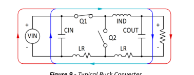
Figure 9 - Typical Buck Converter
The path between the COUT and CIN capacitors is of particular importance since the AC currents are flowing through both of them when Q1 is turned on. Figure 10, schematically, shows the reduced trace length between input and output capacitors. The shorter path lessens the effects that copper trace parasitics can have on the PI33XX performance.
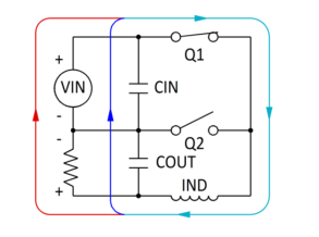
Figure 10 - Current flow: Q1 closed
When Q1 is on and Q2 is off, the majority of CIN’s current is used to satisfy the output load and to recharge the COUT capacitors. When Q1 is off and Q2 is on, the load current is supplied by the inductor and the COUT capacitor as shown in Figure 11. During this period CIN is also being recharged by the VIN. Minimizing CIN loop inductance is important to reduce peak voltage excursions when Q1 turns off. Also, the difference in area between the CIN loop
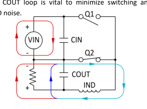
GND noise.
Figure 11 - Current flow: Q2 closed
The recommended component placement, shown in Figure 12, illustrates the tight path between CIN and COUT (and VIN and VOUT) for the high AC return current. This optimized layout is used on the PI33XX evaluation board.
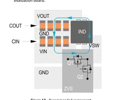
Figure 12 - Recommended component placement and metal routing
800 735.6200 11/2012 Page 39 of 42
Page 40
Recommended PCB Footprint and Stencil
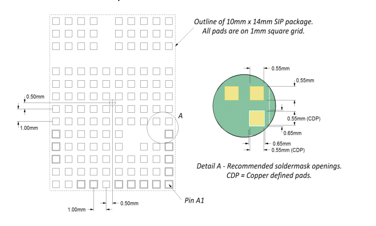
Figure 13 - Recommended Receiving PCB footprint.
Figure 13 details the recommended receiving footprint for PI33XX 10mm x 14mm package. All pads should have a final copper size of 0.55mm x 0.55mm, whether they are solder-mask defined or copper defined, on a 1mm x 1mm grid. All stencil openings are 0.55mm when using a 6mil stencil.
800 735.6200 11/2012 Page 40 of 42
Page 41
Package Drawings
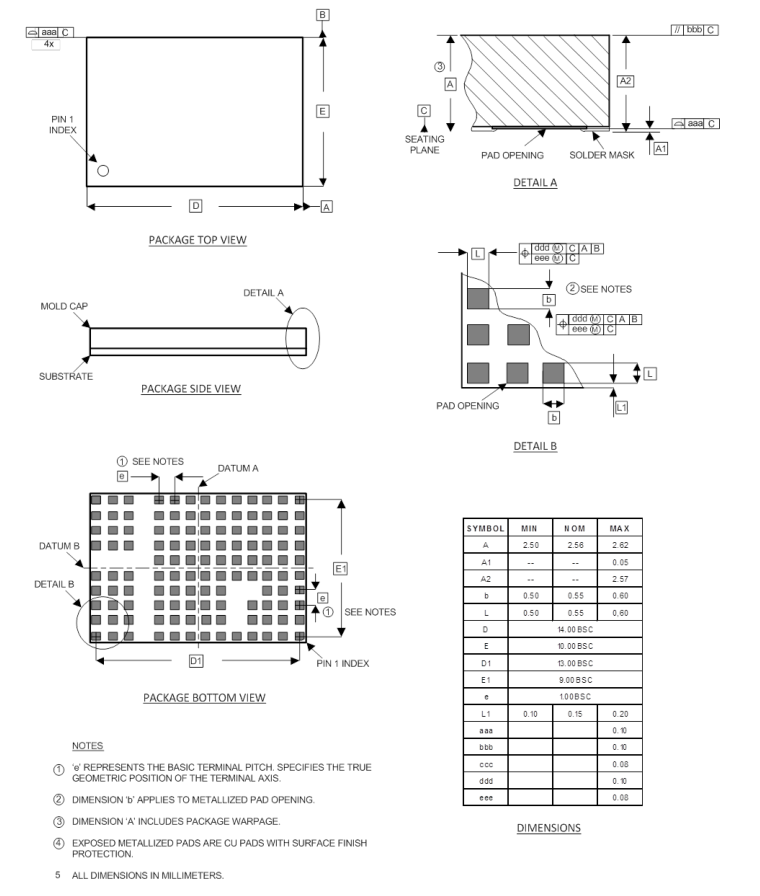
800 735.6200 11/2012 Page 41 of 42
Page 42
Warranty
Information furnished by Vicor is believed to be accurate and reliable. However, no responsibility is assumed by Vicor for its use. Vicor makes no representations or warranties with respect to the accuracy or completeness of the contents of this publication. Vicor reserves the right to make changes to any products, specifications, and product descriptions at any time without notice. Information published by Vicor has been checked and is believed to be accurate at the time it was printed; however, Vicor assumes no responsibility for inaccuracies. Testing and other quality controls are used to the extent Vicor deems necessary to support Vicor’s product warranty. Except where mandated by government requirements, testing of all parameters of each product is not necessarily
performed. Specifications are subject to change without notice.
Vicor’s Standard Terms and Conditions All sales are subject to Vicor’s Standard Terms and Conditions of Sale, which are available on Vicor’s webpage or upon request.
Product Warranty In Vicor’s standard terms and conditions of sale, Vicor warrants that its products are free from non-conformity to its Standard Specifications (the “Express Limited Warranty”). This warranty is extended only to the original Buyer for the period expiring two (2) years after the date of shipment and is not transferable. UNLESS OTHERWISE EXPRESSLY STATED IN A WRITTEN SALES AGREEMENT SIGNED BY A DULY AUTHORIZED VICOR SIGNATORY, VICOR DISCLAIMS ALL REPRESENTATIONS, LIABILITIES, AND WARRANTIES OF ANY KIND (WHETHER ARISING BY IMPLICATION OR BY OPERATION OF LAW) WITH RESPECT TO THE PRODUCTS, INCLUDING, WITHOUT LIMITATION, ANY WARRANTIES OR REPRESENTATIONS AS TO MERCHANTABILITY, FITNESS FOR PARTICULAR
PURPOSE, INFRINGEMENT OF ANY PATENT, COPYRIGHT, OR OTHER INTELLECTUAL PROPERTY RIGHT, OR ANY OTHER MATTER. This warranty does not extend to products subjected to misuse, accident, or improper application, maintenance, or storage. Vicor shall not be liable for collateral or consequential damage. Vicor disclaims any and all liability arising out of the application or use of any product or circuit and assumes no liability for applications assistance or buyer product design. Buyers are responsible for their products and applications using Vicor products and components. Prior to using or distributing any products that include Vicor components, buyers should provide adequate design, testing and operating safeguards.
Vicor will repair or replace defective products in accordance with its own best judgment. For service under this warranty, the buyer must contact Vicor to obtain a Return Material Authorization (RMA) number and shipping instructions. Products returned without prior authorization will be returned to the buyer. The buyer will pay all charges incurred in returning the product to the factory. Vicor will pay all reshipment charges if the product was defective within the terms of this warranty.
Life Support Policy VICOR’S PRODUCTS ARE NOT AUTHORIZED FOR USE AS CRITICAL COMPONENTS IN LIFE SUPPORT DEVICES OR SYSTEMS WITHOUT THE EXPRESS PRIOR WRITTEN APPROVAL OF THE CHIEF EXECUTIVE OFFICER AND GENERAL COUNSEL OF VICOR CORPORATION. As used herein, life support devices or systems are devices which (a) are intended for surgical implant into the body, or (b) support or sustain life and whose failure to perform when properly used in accordance with instructions for use provided in the labeling can be reasonably expected to result in a significant injury to the user. A critical component is any component in a life support device or system whose failure to perform can be reasonably expected to cause the
failure of the life support device or system or to affect its safety or effectiveness. Per Vicor Terms and Conditions of Sale, the user of Vicor products and components in life support applications assumes all risks of such use and indemnifies Vicor against all liability and damages.
Intellectual Property Notice Vicor and its subsidiaries own Intellectual Property (including issued U.S. and Foreign Patents and pending patent applications) relating to the products described in this data sheet. No license, whether express, implied, or arising by estoppel or otherwise, to any intellectual property rights is granted by this document. Interested parties should contact Vicor's Intellectual Property Department. The products described on this data sheet are protected by the following U.S. Patents Numbers: RE 40,072.
Vicor Corporation
Picor Corporation
25 Frontage Road
51 Industrial Drive
Andover, MA, USA 01810 USA
North Smithfield, RI 02896 USA
Customer Service: custserv@vicorpower.com Technical Support: apps@vicorpower.com
800 735.6200 11/2012 Page 42 of 42