
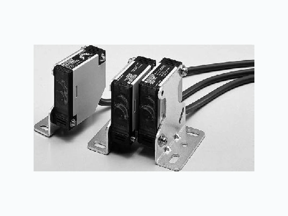
E3JK ETC
Document overview
- Manufacturer or author: Provided By www.digicamel.com(FREE DATASHEET DOWNLOAD SITE)
- PDF pages: 8
Technical content
A-218 Photoelectric Sensors Built-in power supply photoelectric sensor E3JK Wide range voltage power supply Pre-wired type/E3JK
- Slim body full of functions and economically available * The value within the parentheses indicates the sensing distance applied when the E39-R2 reflector is used. Note: The UL-listed model ends with "-US". (Example: E3JK-5M1-US) . Note that the DC transistor type of the E3JK is UL-unlisted. Accessories (Order Separately) Slits Sensor type Shape Connection method Sensing distance Output form Output Model Through-beam Pre-wired models Light ON Relay output E3JK-5M1 Dark ON E3JK-5M2 Light ON/ Dark ON (selectable) DC transistor output NPN: E3JK-5S3 Retroreflective model (with M.S.R. function) * Light ON Relay output E3JK-R2M1 Dark ON E3JK-R2M2 Light ON/Dark ON (selectable) DC transistor output NPN E3JK-R2S3 PNP E3JK-R2R3 Retroreflective model (without M.S.R. function) * Light ON Relay output E3JK-R4M1 Dark ON E3JK-R4M2 Light ON/Dark ON (selectable) DC transistor output (NPN) E3JK-R4S3 Diffuse-reflective Light ON Relay output E3JK-DS30M1 Dark ON E3JK-DS30M2 Light ON/Dark ON (selectable) DC transistor output (NPN) E3JK-DS30S3 Slit width Sensing distance Minimum sensing object (typical) Model Quantity Remarks Width 1 mmx20 mm E3JK-5 ## 0.7 m 1 mm dia. E39-S39 1 pc. each for emitter and receiver (total 2 pcs.) (Seal type long slit) Can be used with the through- beam model E3JK-5##. 2.5m (3m) (5m) 300mm
- Values in parentheses indicate the minimum requi red distance between the sensor and reflector. Note: When the reflector used is other than the supplied one, set the sensing distance to about 0.7 times of the typical example as a guideline. Mounting Brackets Note: If a through-beam model is used, order two Mounti ng Brackets for the emitter and receiver respectively. Name Sensing distance (typical) Model Quantity Remarks Reflectors E3JK-R2## 2.5 m (rated value) E39-R1 1 Attached to the E3JK-R2##. Attached to the E3JK-R4##.E3JK-R4## 4 m (rated value) E3JK-R2## 3 m E39-R2 1 ---E3JK-R4## 5 m Small reflector E3JK-R2 ## 1 m (5 mm) * E39-R3 1 --- Tape Reflector E3JK-R2## 750 mm (200 mm) * E39-RS1 E3JK-R2## 1.5 m (200 mm) * E39-RS3 Shape Model Quantity Remarks E39-L40 1 Supplied with E3JK
A-220 Photoelectric Sensors Rating/Performance E3JK Sensor type Through-beam Retroflective model (with M.S.R. function) Retroflective model (without M.S.R. function) Diffuse-reflective Item Model E3JK-5M# E3JK-5S3 E3JK-R2M# E3JK-R2#3 E3JK-R4M# E3JK-R4S3 E3JK-DS30M# E3JK-DS30S3 Sensing distance 5 m 2.5 m (When using the E39-R1) 4 m (When using the E39-R1) 300 mm (White paper 100x100 mm) Standard sensing Differential distance --- 20% max. of sensing distance Directional angle Both emitter and receiver: 3°C to 20°C 1° to 5° --- Light source (wave length) Infrared LED (950 nm) Red LED (660 nm) Infrared LED (950 nm) Power supply voltage 12 to 240 VDC ±10% ripple (p-p) : 10% max. 24 to 240 VAC ±10% 50/60 Hz Cur- rent con- sump- tion DC 3 W max. 2 W max. AC 3 W max. 2 W max. Control output Relay output: 250VAC
3 A (cosj=1)
max., 5 VDC 10 mA min. DC SSR Negative common
48 VDC
100 mA max. Leak current 0.1 mA max. With load short-circuit protection Relay output: 250VAC max., 5 VDC 10 mA min. DC SSR Negative or positive common 100 mA max. Leak current 0.1 mA max. With load short-circuit protection Relay output: 250VAC max., 5 VDC 10 mA min. DC SSR Negative common 100 mA max. Leak current 0.1 mA max. With load short-circuit protection Relay output: 250VAC max., 5 VDC 10 mA min. DC SSR Negative common 100 mA max. Leak current 0.1 mA max. With load short-circuit protection Life ex- pect- ancy (relay output) Me- chani- cal 50 million times or more (switching frequency 18,000 times/hour) Electri- cal 100 thousand times or more (switching frequency 18,000 times/hour) Sensitivity adjustment --- Single-turn adjustment Ambient illuminance Incandescent lamp: 3,000 lux max. Ambient temperature Operating: -25°C to 55°C, Storage: -30°C to 70°C (with no icing or condensation) Ambient humidity Operating: 45% to 85%RH, Storage: 35% to 95%RH (with no condensation) Insulation resistance 20 M W min. at 500 VDC Dielectric strength 1,500 VAC at 50/60 Hz for 1 minute Vibra- tion resis- tance De- struc- tion 10 to 55 Hz, 1.5 mm double amplitude for 2 hours each in X, Y, and Z directions Mal- function 10 to 55 Hz, 1.5 mm double amplitude for 2 hours each in X, Y, and Z directions
Destruction: 500 m/s 2 for 3 times each in X, Y, and Z directions Mal- function Destruc- tion: 100m/s2 (approx. 10G) 3 times each in X, Y, and Z directions Destruction: 500 m/s 2 for 3 times each in X, Y, and Z directions Destruction: 100m/s (approx. 10G) 3 times each in X, Y, and Z direc tions Destruction: 500 m/s 2 for 3 times each in X, Y and Z directions Destruction: 100m/s (approx. 10G) 3 times each in X, Y, and Z direc tions Destruction: 500 m/s 2 for 3 times each in X, Y, and Z directions Destruction: 100m/s (approx. 10G) 3 times each in X, Y, and Z direc tions Destruction: 500 m/s 2 for 3 times each in X, Y, and Z directions Protective structure IEC60529 IP64 Connection method Pre-wired models (standard length: 2 m) Weight (Packed state) Approx. 420 g Approx. 250 g Materi- al Case ABS Lens Acrylics Mount- ing bracket Steel Accessories Mounting bracket (with screws), nuts, instruction manual, reflector (retroreflective model only) Sensor type Through-beam Retroflective model (with M.S.R. function) Retroflective model (without M.S.R. function) Diffuse-reflective Item Model E3JK-5M# E3JK-5S3 E3JK-R2M# E3JK-R2#3 E3JK-R4M# E3JK-R4S3 E3JK-DS30M# E3JK-DS30S3
A-222 Photoelectric Sensors Characteristic data (typical) Excess Gain Ratio vs. Setting Distance Through-beam model Retroreflect ive Models Diffuse-reflective E3JK-5## E3JK-R2## + E39-R1 (supplied reflector) E3JK-DS30 ## E3JK-R4## + E39-R1 (supplied reflector) 1,000 500 300 100 Setting distance (m) 102 3 4 5 6 7 8 Operating voltage Excess gain ratio 100 Setting distance (m) 102 3 4 Operating voltage Reflector: E39-R1 Excess gain ratio Setting distance (mm) 1000 200 300 400 500 100 1Operating voltage Sensing object: White paper Excess gain ratio Setting distance (m) 102 3 4 5 100 1Operating voltage Reflector: E39-R1 Excess gain ratio
Note: Connect to brown and blue on the emitter side. Model Timing chart Output circuit E3JK-5M1 E3JK-5M2 E3JK-R2M1 E3JK-R2M2 E3JK-R4M1 E3JK-R4M2 E3JK-DS30M1 E3JK-DS30M2Model Timing chart Output circuit E3JK-5S3 E3JK-R2S3 E3JK-R4S3 E3JK-DS30S3 E3JK-R2R3 Light indicator (red) L-ON(Ta) (E3JK-##M1) D-ON(Ta) (E3JK-##M2) Incident Interrupted ON OFF ON OFF ON OFF Power sourceMain circuit (Polarity Optional) 24 to 240 VAC 12 to 240 VDC White Brown Blue Black Contact output Tc Tb Ta Gray Built-in relay: G6C Light indicator (red) L-ON mode D-ON mode Incident Interrupted ON OFF ON OFF ON OFF Main circuit Power source Load Load Brown Blue White Gray (D-ON) Black (L-ON) Drive circuit Drive circuit 24 to 240 VAC 12 to 240 VDC Light indicator (red) L-ON mode D-ON mode Incident Interrupted ON OFF ON OFF ON OFF Power source (Polarity Optional) 24 to 240 VAC 12 to 240 VDC Main circuit Drive circuit Drive circuit D/ON L/ON Gray Black 48 VDC max. White Load Load I1 + I2 < 100 mA Brown Blue Note: The output stage leakage currents are 0.1 mA max., respectively.
A-224 Photoelectric Sensors Operation Adjustment Precautions Design Power Reset Time The Sensor is ready to detect an object within 200 ms after it is turned ON. If Sensor and load are connected to separate power supplies, ensure to turn ON the Sensor first. Wiring Considerations Connection/Wiring If the DC transistor output type is used, the sum of load cur- rents of L-ON output (NO) a nd D-ON output (NC) should be within 100 mA. If the sum of load currents exceeds 100 mA, the load short-circuit protecti on may be activated. (The load short-circuit protection is reset by turning OFF the power of the photoelectric sensor.) Miscellaneous Ambient Conditions (Installation Area) The E3JK will malfunction if installed in the following places.
- Places where the E3JK is exposed to a dusty environment.
- Places where corrosive gases are produced.
- Places where the E3JK is directly exposed to water, oil, or chemicals. Item Through-beam Retroreflective Models Diffuse-reflective Model E3JK Swing the receiver and emitter ver- tically and/or horizontally and set the adjuster in the center of the range where the indicator of the re- ceiver turns ON. Like the through-beam model, ad- just the reflector and emitter/re- ceiver. Since the directional angle of the emitter/receiver is 1 to 5°, ad- just the emitter/receiver especially carefully. (1) If you have a sensing object as shown in the figure, turn the sensitivity adjuster clockwise (increase the sensitivity) until the indicator is turned ON, and define this adjuster position as (A). (2) Remove the sensing object, turn the sensitivity adjuster clockwise until the indicator is turned ON by a background object, and define this posi- tion as (B). (3) Turn the sensitivity adjuster counterclockwise (decrease the sensitivity) from (B) until the indicator is turned OFF, and define this position as (C). (4) The position in the middle of (A) and (C) is the optimum position. If the indicator is not turned ON by the background object at the maximum sensitivity, set the adjuster in the middle of (A) and maximum sensitivity. ∑ The sensitivity adjuster may be damaged if an excessive force is applied. Correct Use With sensing object Without sensing object Operation Sensitivity MIN MAX Reset Operation (C)(C) (A) (A) Setting (B) Background object Sensitivity MIN MAX (A) Sensitivity MIN MAX E3JK Emitter Receiver Emitter Receiver
Dimensions (Unit: mm) Sensors Accessories (Order Separately) Seal type long slit (for E3JK) 10˚ R56.6 Optical axis 36.5 21.5 Steel 13.4 2850 Lens 14.8 dia. Indicator *218 49 1 8 6 dia. 6.4 40 12 6.4 * 1.Mounting brackets can be used on the A side (Two, M4 x 20 attached) . * 2.Emitter: Power indicator Receiver: Light indicator * 3.Emitter includes 2-conductor. (A)*1 2-M6 6-dia., 5-conductor, vinyl-insulated round cable (conductor cross-sectional area: 0.3 mm²; insulation diameter: 1.5 mm). Standard length: 2 m. * 3 CAD file E3JK_01E3JK-5## Mounting Holes With Mounting Bracket Attached Emitter: E3JK-5L Receiver: E3JK-5D## Sensitivity adjustment volume * 2 10˚ R56.6 Optical axis Steel 13.4 2850 Lens Light indicator18 49 1 8 6 dia. 6.4 40 12 6.4 Emitter Receiver * 1. Mounting brackets can be used on the A side (Two, M4 x 20 attached) . * 2. No sensitivity adjustment volume on the retororeflective model. (A)*1 2-M6 6-dia., 5-conductor, vinyl-insulated round cable (conductor cross-sectional area: 0.3 mm²; insulation diameter: 1.5 mm). Standard length: 2 m. * 3 E3JK-R2## E3JK-R4## E3JK-DS30## v CAD file E3JK_02 With Mounting Bracket Attached Mounting Holes E39-S39 Material: Polyester 0.1 mm thick 20 26.5 1±0.1