
HZ VISHAY
Document overview
- Manufacturer or author: Provided By www.digicamel.com(free datasheet download site)
- PDF pages: 5
Technical content
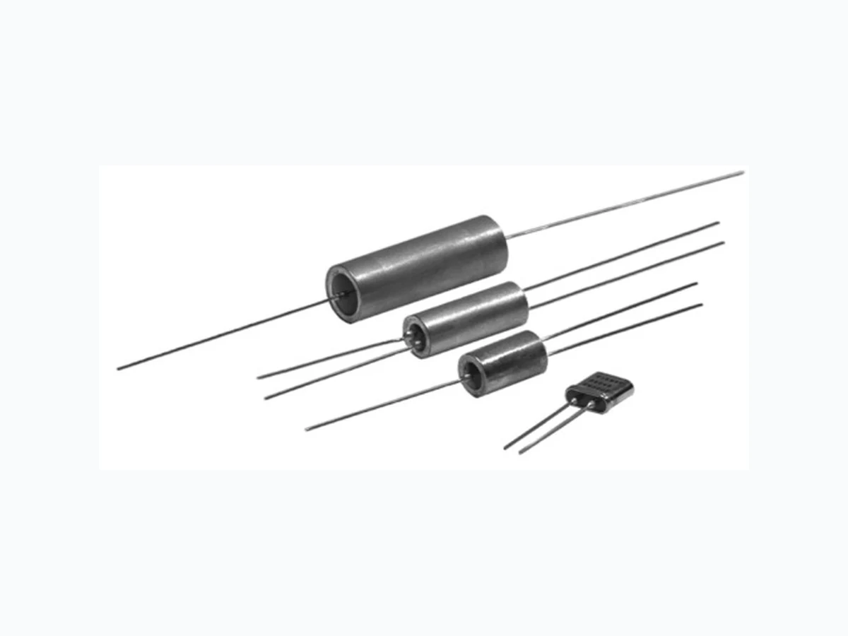
Document Number: 63120 For any ques tions, contact: foil@vishay.com www.vishay.com Revision: 17-Jun-08 1 HZ Series (Z-Foil) Vishay Foil Resistors Hermetically Sealed Ultra High Precision Z-Foil Technology Resistors with TCR of ± 0.2 ppm/°C , Tolerance of ± 0.001 % and Load Life Stability of ± 0.005 % Any value available within resistance range INTRODUCTION The Z-foil based oil filled, hermetically sealed HZ-series resistors represent an indust ry breakthrough. The hermetic sealing eliminates the ingress of moisture and oxygen, while the oil acts as a thermal conductor, thus eliminating long term degradation elements of unsealed resistors, while at the same time allowing the device to accept short periods of overload without degradation. The Z-foil technology provides a significant reduction of the resistive components sensitiv ity to ambient temperature variations (TCR) and applied power changes (PCR). When combined with the hermetic sealing and oil filling, the H-series resistors become the most prec ise and stable resistors available. With accuracies of ± 0.001 % and a resistance range from 5 Ω to 1.1 M Ω and long term shelf life of less than 2 ppm, these devices are virtually secondary standards that can be carried in sets for daily or periodic calibration of factory measurement equipment. The VHA series is also available with laboratory and metrology level precision an d long term stability with additional in-house orient ed process such as: special TCR plotting, mounted chip stabilization, thermal shock and bake prior to sealing, co mbined thermal shock and power conditioning on finished product, thermal and power conditioning, component linearity test. Note 1. For lower TCR and for selected TCR tracking, please contact us
FEATURES
- Temperature coefficient of resistance (TCR): ± 0.2 ppm/°C typical (- 55 °C to + 125 °C, + 25 °C ref.)
- Power coefficient “ΔR due to self heating”: 5 ppm at rated power
- Tolerance: to ± 0.001 %
- Load life stability ± 0.002 % maximum ΔR (60 °C for 2000 h at 0.1 W per chip)
- Electrostatic discharge (ESD) > 25 000 V
- Resistance range: 5 Ω to 1.1 MΩ (higher or lower values of resistance available)
- Power rating: 0.3 to 2.5 W at + 25 °C (depending on model - see table 2)
- Shelf life stability: 2 ppm for at least 10 years
- Non inductive, non capacitive design
- Non hot spot design
- Rise time: 1.0 ns without ringing
- Current noise: < - 40 dB
- Thermal EMF: 0.05 µV/°C typical
- Voltage coefficient: < 0.1 ppm/V
- Non inductive: < 0.08 µH
- Terminal finishes available: lead (Pb)-free tin/lead alloy
- Impervious to harmful environments - oil filled
- For better performances, please contact us TABLE 1 - TOLERANCE AND TCR VS. RESISTANCE VALUE RESISTANCE VALUE (Ω) TYPICAL TCR AND MAX. SPREAD (ppm/°C)1) 100 to < 1M1 ± 0.2 ± 2 50 to < 100 ± 0.2 ± 3 5 to < 50 ± 0.2 ± 4 FIGURE 1 - TRIMMING TO VALUES (Conceptual Illustration) Mutual Inductance Reduction due to Opposing Current in Adjacent Lines Current Path Before Trimming Note: Foil shown in black, etched spaces in white Interloop Capacitance Reduction in Series Trimming Process Removes this Material from Shorting Strip Area Changing Current Path and Increasing Resistance Current Path After Trimming
HZ Series (Z-Foil) Vishay Foil Resistors Hermetically Sealed Ultra High Precision Z-Foil Technology Resistors with TCR of ± 0.2 ppm/°C , Tolerance of ± 0.001 % and Load Life Stability of ± 0.005 % www.vishay.com For any questions, contact: foil@vishay.com Document Number: 63120
2 Revision: 17-Jun-08
- Available in a 4-lead terminal: VHA512 please use 302073Z VHA516 please use 302074Z VHA518 please use 302075Z ** 0.375 H available See next page for numbered footnotes TABLE 2 - MODEL SELECTION MODEL NUMBER RESISTANCE RANGE (Ω) STANDARD RESISTANCE TOLERANCE MAXIMUM WORKING VOLTAGE2) POWER RATING at + 25 °C AVERAGE WEIGHT (g) CONSTRUCTION BRIEF DIMENSIONS3) TIGHTEST (Ω) LOOSEST (%) INCHES mm VHP202Z VHP202ZJ 10 to 66k 66K to 100K 300 0.3 W 0.2 W
1.4 Oil-filled, tinned
copper leads, nickel shell, kovar and glass header W: 0.185 ± 0.020 L: 0.435 ± 0.020 H: 0.430 ± 0.020** LL: 1.000 ± 0.125 LS: 0.150 ± 0.010 ST: 0.095 Max. 4.70 ± 0.51 11.05 ± 0.51 10.92 ± 0.51 25.4 ± 3.18 3.81 ± 0.25 2.41 Max. VHA412Z 10 to 66K 66K to 100K 250 0.3 W 0.2 W 4.6 Oil-filled, tinned copper leads, tinned brass shell, kovar and glass end bells L: 0.625 ± 0.031 D: 0.375 ± 0.031 LL: 1.000 Min. 15.88 ± 0.79 9.53 ± 0.79 25.4 Min. VHA414Z 5 to 120K > 120K to 200K 1K to 1) 500 to < 1K 50 to < 500 30 to < 50 20 to < 30 10 to < 20 5 to < 10 ± 0.001 ± 0.1 ± 0.0025 ± 0.1 ± 0.005 ± 0.1 ± 0.01 ± 0.1 ± 0.02 ± 0.1 ± 0.05 ± 0.1 ± 0.1 ± 0.1 350 0.5 W 0.3 W 7.3 L: 1.000 ± 0.031 D: 0.375 ± 0.031 LL: 1.000 Min. 25.4 ± 0.79 9.53 ± 0.79 25.4 Min. VHA512Z* 5 to 180K 180K to 300K 350 0.75 W 0.4 W 6.3 L: 0.625 ± 0.031 D: 0.500 ± 0.031 LL: 1.000 Min. 15.88 ± 0.79 12.7 ± 0.79 25.4 Min. VHA516-4Z* VHA516-5Z* VHA516-6Z* 5 to 240K > 240K to 400K 5 to 300K > 300K to 500K 5 to 360K > 360K to 600K 500 1.0 W 0.5 W 1.25 W 0.6 W 1.5 W 0.7 W 9.2 L: 1.000 ± 0.031 D: 0.500 ± 0.031 LL: 1.000 Min. 25.4 ± 0.79 12.7 ± 0.79 25.4 Min. VHA518-7Z* VHA518-8Z* VHA518-9Z* VHA518-10Z* VHA518-11Z* 5 to 420K > 420K to 700K 5 to 480K > 480K to 800K 5 to 540K > 540K to 900K 5 to 600K > 600K to 1.0M 5 to 660K > 660K to 1.1M 600 1.75 W 0.8 W 2.0 W 0.9 W 2.25 W 1.0 W 2.5 W 1.1 W 2.5 W 1.2 W 13.5 L: 1.500 ± 0.031 D: 0.500 ± 0.031 LL: 1.000 Min. 38.1 ± 0.79 12.7 ± 0.79 25.4 Min. FIGURE 2 - TYPICAL TCR CURVE Z-FOIL + 500 + 200 + 100 - 100 - 200 - 300 - 500 - 55 - 25 + 25 + 60 + 75 + 100 + 125 Ambient Temperature (°C) R (ppm) 0.05 ppm/°C - 0.1 ppm/°C 0.1 ppm/°C 0.14 ppm/°C 0.2 ppm/°C- 0.16 ppm/°C- 400 + 300 + 400 FIGURE 3 - POWER DERATING CURVE + 100 + 75 + 50 + 25 - 50 - 25 0 + 25 + 50 + 75 + 100 + 125 + 150 + 175 Percent of Rated Power - 55 °C Ambient Temperature (°C)
Document Number: 63120 For any ques tions, contact: foil@vishay.com www.vishay.com Revision: 17-Jun-08 3 HZ Series (Z-Foil) Hermetically Sealed Ultra High Precision Z-Foil Technology Resistors with TCR of ± 0.2 ppm/°C , Tolerance of ± 0.001 % and Load Life Stability of ± 0.005 % Vishay Foil Resistors Notes 1. Upper end of resistance range varies with m odel selected (i.e. VHP202Z; the range is to 100 k Ω; VHA518-10Z, the range is to 1.0 M Ω) per Table 2 2. Not to exceed power rating of resistor 3. Insulating sleeve - a special case insula ting plastic sleeve is available on VHAZ mo dels - specify letter “P” as a suffix to model number (i.e. VHA412ZP) 4. 0.200" (5.08 mm) lead spacing available - specify VHP202ZJ 5. Inductance (L) due mainly to the leads 6. The resolution limit of existing test equipment (within me asurement capability of the equipment, or “essentially zero”) 7. µV/° relates to EMF due to lead temperature diff erence and µV/watt due to power applied to the resistor 8. Load life ΔR max. can be reduced through in-house oriented processes FIGURE 4 - STANDARD IMPRINTING AND DIMENSIONS LS Model Number VISHA Y XXXX VHP202Z ST H L Date Code W Front View Rear View Lead Material #22 AWG Round Solder Coated Copper Resistance Value Code Tolerance Serial No. 100R01 0.01% XXXX Week Year LL Lead Material #22 AWG Round Solder Coated Copper Tolerance Model No. Resistance Value Code Date Code Week Year VISHA Y XXXX VHA412Z 100R01 0.005% D LL L TABLE 3 - “H” SERIES SPECIFICATIONS Stability8) Load life at 2000 h ± 0.002 % maximum ΔR at 0.1 W per chip and at + 60 °C Shelf life ± 2 ppm (0.0002 %) after at least 10 years Current Noise < 0.010 µV (RMS)/V of applied voltage (- 40 dB) High Frequency Operation Rise time 1.0 ns without ringing Inductance (L) 5) 0.1 µH maximum; 0.08 µH typical Capacitance (C) 1.0 pF maximum; 0.5 pF typical Voltage Coefficient < 0.1 ppm/V Thermal EMF7) 0.1 µV/°C maximum; 0.05 µV/°C typical; 1 µV/W maximum Hermeticity 10-7 atmospheric cc/s maximum
HZ Series (Z-Foil) Vishay Foil Resistors Hermetically Sealed Ultra High Precision Z-Foil Technology Resistors with TCR of ± 0.2 ppm/°C , Tolerance of ± 0.001 % and Load Life Stability of ± 0.005 % www.vishay.com For any questions, contact: foil@vishay.com Document Number: 63120
4 Revision: 17-Jun-08
- Application engineering release: for non-standard requests, please contact application engineering. TABLE 4 - GLOBAL PART NUMBER INFORMATION NEW GLOBAL PART NUMBER: Y1750120K500V9L (preferred part number format) DENOTES PRECISION VALUE AER* YR = Ω K = kΩ M = MΩ 0 = standard product, tin/lead termination 1 = with plastic sleeve, tin/lead termination 9 = standard product, lead (Pb)-free termination 19 = with plastic sleeve, lead (Pb)-free termination Other = custom PRODUCT CODE RESISTANCE TOLERANCE PACKAGING 6071 = VHP202Z 1748 = VHP202ZJ 1749 = VHA412Z 1751 = VHA414Z 1750 = VHA512Z 1752 = VHA516-4Z 1753 = VHA516-5Z 1754 = VHA516-6Z 1755 = VHA518-7Z 1756 = VHA518-8Z 1757 = VHA518-9Z 1758 = VHA518-10Z 1759 = VHA518-11Z S = ± 0.001 % U = ± 0.002 % X = ± 0.0025 % V = ± 0.005 % T = ± 0.01 % Q = ± 0.02 % A = ± 0.05 % B = ± 0.1 % C = ± 0.25 % D = ± 0.5 % F = ± 1.0 % L = bulk pack FOR EXAMPLE: ABOVE GLOBAL ORDER Y1750 120K500 V 9 L: TYPE: VHA512Z VALUE: 120.5 kΩ ABSOLUTE TOLERANCE: ± 0.005 % TERMINATION: lead (Pb)-free PACKAGING: bulk pack HISTORICAL PART NUMBER: VHA512ZT 120K50 V B (will continue to be used) VHA512Z T 120K50 V B MODEL TERMINATION PLASTIC SLEEVE OHMIC VALUE TOLERANCE PACKAGING VHP202Z VHP202ZJ VHA412Z VHA414Z VHA512Z VHA516-4Z VHA516-5Z VHA516-6Z VHA518-7Z VHA518-8Z VHA518-9Z VHA518-10Z VHA518-11Z T = lead (Pb)-free None = tin/lead P = plastic sleeve None = standard 120K50 = 120.5 kΩ S = ± 0.001 % U = ± 0.002 % X = ± 0.0025 % V = ± 0.005 % T = ± 0.01 % Q = ± 0.02 % A = ± 0.05 % B = ± 0.1 % C = ± 0.25 % D = ± 0.5 % F = ± 1.0 % B = bulk pack 7501 0K5 2 V90 L
Document Number: 91000 www.vishay.com Revision: 18-Jul-08 1 Disclaimer Legal Disclaimer Notice Vishay All product specifications and data are subject to change without notice. Vishay Intertechnology, Inc., its affiliates, agents, and employees, and all persons acting on its or their behalf (collectively, “Vishay”), disclaim any and all liability for any errors, inaccuracies or incompleteness contained herein or in any other disclosure relating to any product. Vishay disclaims any and all li ability arising out of the use or application of any product described herein or of any information provided herein to the maximum extent permit ted by law. The product specifications do not expand or otherwise modify Vishay’s terms and conditions of purcha se, including but not limited to the warranty expressed therein, which apply to these products. No license, express or implied, by estoppel or otherwise, to any intellectual property rights is granted by this document or by any conduct of Vishay. The products shown herein are not designed for use in medi cal, life-saving, or life-sustaining applications unless otherwise expressly indicated. Customers using or selling Vishay products not expressly indicated for use in such applications do so entirely at their own risk and agree to fully indemnify Vishay for any damages arising or resulting from such use or sale. Please contact authorized Vishay personnel to obtain written terms and conditions regarding products designed for such applications. Product names and markings noted herein may be trademarks of their respective owners.