
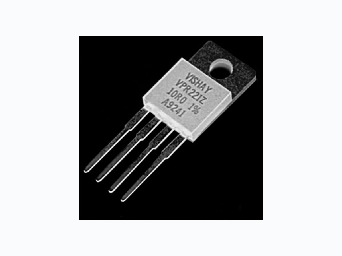
VPR221Z_V01 VISHAY
Document overview
- Manufacturer or author: Provided By www.digicamel.com(free datasheet download site)
- PDF pages: 4
Technical content
Ultra High Precision Z-Foil Power Resistor in TO-220 Configuration with TCR of ± 0.05 ppm/°C, PCR of 4 ppm/W and Load Life Stability of ± 0.005 % (50 ppm) VPR221Z (Z-Foil) Vishay Foil Resistors Document Number: 63116 For any questions, contact: foil@vishaypg.com www.foilresistors.com Revision: 25-Mar-10 1 IMPR OVED PRODUC T Any value at any tolerance available within resistance range INTRODUCTION The Z-Foil Technology provides a significant reduction of the resistive component’s sensitiv ity to ambient temperature variations (TCR) and applied power changes (PCR). VPR221Z provides high rated power, excellent load life stability , low Temperature Coefficient (TCR) and low Power Coefficient (PCR) - all in one resistor. ± 0.05 ppm/°C Absolute TCR removes error due to temperature gradients. By taking advantage of the overall stability and reliability of Bulk Metal ® Z-Foil resistors, designers can significantly reduce circuit errors and greatly improve overall circuit performances. Model VPR221Z is a 4 lead kelvin connected device. Our Application Engineering Department is available to advise and make recommendations. For non-standard technical requirements and special applications, please contact us. Notes 1. MIL-Range (- 55 °C to + 125 °C, + 25 °C Ref.) Contact Applications Engineer ing for other available values
FEATURES
Temperature coefficient of resistance (TCR): ± 0.05 ppm/°C typical (0 °C to + 60 °C) ± 0.2 ppm/°C typical (- 55 °C to + 125 °C, + 25 °C ref.) (see table 1) Tolerance: to ± 0.01 % Power coefficient “R due to self heating” 4 ppm/W typical Rated power: 8 W chassis mounted (MIL-PRF-39009) Load life stability: to ± 0.005 % at 25 °C for 2000 hours, at 1.5 W Resistance range: 0.5 to 500 Electrostatic discharge (ESD) above 25 000 V Short time overload 0.001 % (10 ppm) Non-inductive, non-capacitive design Rise time: 1 ns without ringing Current noise <- 40 dB Thermal EMF: 0.05 µV/°C typical Voltage coefficient < 0.1 ppm/V Non inductive: < 0.08 µH Non hot spot design Terminal finishes available: lead (Pb)-free tin/lead alloy Any value available within resistance range (e.g. 1K234) For better performances please contact us
APPLICATIONS
Automatic test equipment (ATE) High precision instrumentation Electron beam application Current sensing applications Pulse applications Military Power amplifier Power supplies * Pb containing terminations are not RoHS compliant, exemptions may apply TABLE 1 - TCR AND TOLERANCE RESISTANCE RANGE () TIGHTEST RESISTANCE TOLERANCE TYPICAL TCR AND MAX. SPREAD1) 10 to 500 ± 0.01 % ± 0.2 ppm/°C ± 1.8 ppm/°C FIGURE 1- POWER DERATING CURVE I1 E1 E2 I2 R V II Ambient Temperature (°C) 100 r e w o P d e t a R f o t n e c r e P - 75 150 - 25 25 75 125- 50 0 50 100 - 55 °C
VPR221Z (Z-Foil) Vishay Foil Resistors www.foilresistors.com For any questions, contact: foil@vishaypg.com Document Number: 63116
2 Revision: 25-Mar-10
A surface mount version of this product is available see data sheets for VPR220S, VPR221S Notes TCR. 2. Whichever is lower. 3. Heat sink chassis dimens ions are requirements per MIL-R-39009/1B: 4. Inductance (L) mainly due to the leads. 5. The resolution limit of existing test requirement (within the measurement capability of the equipment, “essentially zero”). 6. µV/°C relates to EMF due to lead temperature difference. FIGURE 2 - TRIMMING TO VALUES (Conceptual Illustration) Mutual Inductance Reduction due to Change in Current Direction Current Path Before Trimming Note: Foil shown in black, etched spaces in white Interloop Capacitance Reduction in Series Trimming Process Removes this Material from Shorting Strip Area Changing Current Path and Increasing Resistance Current Path After Trimming FIGURE 3 - TYPICAL TCR CURVE Z-FOIL (for more details see table 1) + 500 + 200 + 100 - 100 - 200 - 300 - 500 - 55 - 25 + 25 + 60 + 75 + 100 + 125 Ambient Temperature (°C) ΔR R (ppm) 0.05 ppm/°C - 0.1 ppm/°C 0.1 ppm/°C 0.14 ppm/°C 0.2 ppm/°C - 0.16 ppm/°C - 400 + 300 + 400 FIGURE 4 - VPR221Z DIMENSIONS in inches (millimeters) TABLE 2 - SPECIFICATIONS Power Rating at + 25 °C
8 W or 3 A2) on heat sink3)
1.5 W in free air
Further derating not necessary. Current Noise < 0.010 µV (rms)/V of applied voltage (- 40 dB) High Frequency Operation Rise Time Inductance 4) (L) Capacitance (C) 0.2 ns at 1 W 0.1 µH maximum: 0.03 µH typical1) 1.0 pF maximum: 0.5 pF typical1) Voltage Coefficient5) < 0.1 ppm/V Operating Temperature Range - 55 °C to + 150 °C Maximum Working Voltage 300 V, Not to exceed power rating Thermal EMF6) 0.15 µV/°C maximum (lead effect) Weight 1.2 g maximum 0.050 ± 0.005 (1.27 ± 0.13) 0.150 ± 0.008 (3.81 ± 0.20)
0.615 Max
(15.62) 0.078 ± 0.005 (1.98 ± 0.13) 0.015 ± 0.002 (0.76 ± 0.05) 0.100 ± 0.005 (2.54 ± 0.13) 0.400 ± 0.010 (10.16 ± 0.25) VISHAY VPR221Z 1R0 1 % 0101 0.245 ± 0.010 (6.22 ± 0.25) 0.141 ± 0.005 Dia (3.58 ± 0.13) 0.540 ± 0.040 (13.72 ± 1.02) 0.115 ± 0.005 (2.92 ± 0.13) 0.050 ± 0.005 (1.27 ± 0.13) 0.200 ± 0.030 (5.08 ± 0.76) E1 I2I1 DIMENSIONS inches mm L 6.00 152.4 W 4.00 101.6 H 2.00 50.8 T 0.04 1.0
VPR221Z (Z-Foil) Vishay Foil Resistors Document Number: 63116 For any questions, contact: foil@vishaypg.com www.foilresistors.com Revision: 25-Mar-10 3 IMPR OVED PRODUC T Note 1. Measurement error ± 0.001 Note * For non-standard requests, please contact Application Engineering. TABLE 3 - PERFORMANCE SPECIFICATIONS1) MIL-PRF 39009 TEST OR CONDITION MIL-PRF 39009 TYPICAL R MAXIMUM R Low temperature storage 24 hours at - 55 °C ± 0.3 % + 0.01 ± 0.001 % (10 ppm) ± 0.002 % (20 ppm) Dielectric withstanding voltage 300 V AC at Atm ± 0.2 % + 0.01 ± 0.001 % (10 ppm) ± 0.002 % (20 ppm) Dielectric withstanding voltage 200 V AC at Brm ± 0.2 % + 0.01 ± 0.001 % (10 ppm) ± 0.002 % (20 ppm) Insulation resistance > 10 4 M > 104 M Low temperature operation ± 0.3 % + 0.01 ± 0.002 % (20 ppm) ± 0.008 % (80 ppm) Short time overload 5 x rated power for 5 seconds (in air) ± 0.3 % + 0.01 ± 0.001 % (10 ppm) ± 0.002 % (20 ppm) Moisture resistance + 65 °C to - 10 °C, 90 to 98 Rh, 10 days ± 0.5 % + 0.01 ± 0.005 % (50 ppm) ± 0.015 % (150 ppm) Terminal Strength ± 0.2 % + 0.01 ± 0.001 % (10 ppm) ± 0.002 % (20 ppm) Load life 8 W at + 25 °C, 2000 hours with heat sink ± 1.0 % + 0.01 ± 0.005 % (50 ppm) ± 0.015 % (150 ppm) High temperature exposure + 150 °C ± 1.0 % + 0.05 ± 0.005 % (50 ppm) ± 0.01 % (100 ppm) TABLE 4 - GLOBAL PART NUMBER INFORMATION NEW GLOBAL PART NUMBER: Y1690420R220T9L (preferred part number format) DENOTES PRECISION VALUE AER* YR = 0 = standard 9 = lead (Pb)-free 1 to 999 = custom PRODUCT CODE RESISTANCE TOLERANCE PACKAGING 1690 = VPR221Z T = ± 0.01 % Q = ± 0.02 % A = ± 0.05 % B = ± 0.1 % C = ± 0.25 % D = ± 0.5 % F = ± 1.0 % L = bulk pack FOR EXAMPLE: ABOVE GLOBAL ORDER Y1690 420R220 T 9 L: TYPE: VPR221Z VALUE: 420.22 ABSOLUTE TOLERANCE: ± 0.01 % TERMINATION: Lead (Pb)-free PACKAGING: Bulk Pack HISTORICAL PART NUMBER: VPR221Z T 420R22 TCR0.2 T B (will continue to be used) VPR221Z T 420R22 TCR0.2 T B MODEL TERMINATION OHMIC VALUE TCR CHARACTERISTIC ABSOLUTE TOLERANCE PACKAGING T = lead (Pb)-free none = tin/lead 420.22 TCR0.2 T = ± 0.01 % Q = ± 0.02 % A = ± 0.05 % B = ± 0.1 % C = ± 0.25 % D = ± 0.5 % F = ± 1.0 % B = bulk pack 6904 0R2 2Y1 T92 L0
Vishay Precision Group, Inc. www.vpgsensors.com Legal Disclaimer Notice Document No.: 63999 Revision: 15-Jul-2014 Disclaimer ALL PRODUCTS, PRODUCT SPECIFICATIONS AND DATA ARE SUBJECT TO CHANGE WITHOUT NOTICE. Vishay Precision Group, Inc., its affiliates, agents, and employees, and all persons acting on its or their behalf (collectively, “VPG”), disclaim any and all liability for any errors, inaccuracies or incompleteness contained herein or in any other disclosure relating to any product. The product specifications do not expand or otherwise modify VPG’s terms and conditions of purchase, including but not limited to, the warranty expressed therein. VPG makes no warranty, representation or guarantee other than as set forth in the terms and conditions of purchase. To the maximum extent permitted by applicable law, VPG disclaims (i) any and all liability arising out of the application or use of any product, (ii) any and all liability, including without limitation special, consequential or incidental damages, and (iii) any and all implied warranties, including warranties of fitness for particular purpose, non-infringement and merchantability. Information provided in datasheets and/or specifications may vary from actual results in different applications and performance may vary over time. Statements regarding the suitability of products for certain types of applications are based on VPG’s knowledge of typical requirements that are often placed on VPG products. It is the customer’s responsibility to validate that a particular product with the properties described in the product specification is suitable for use in a particular application. You should ensure you have the current version of the relevant information by contacting VPG prior to performing installation or use of the product, such as on our website at vpgsensors.com. No license, express, implied, or otherwise, to any intellectual property rights is granted by this document, or by any conduct of VPG. The products shown herein are not designed for use in life-saving or life-sustaining applications unless otherwise expressly indicated. Customers using or selling VPG products not expressly indicated for use in such applications do so entirely at their own risk and agree to fully indemnify VPG for any damages arising or resulting from such use or sale. Please contact authorized VPG personnel to obtain written terms and conditions regarding products designed for such applications. Product names and markings noted herein may be trademarks of their respective owners. Copyright Vishay Precision Group, Inc., 2014. All rights reserved. Disclaimer Legal Disclaimer Notice