
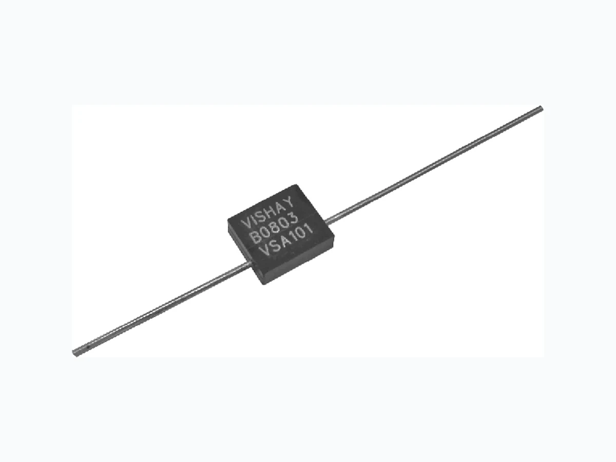
VSA101 VISHAY
Document overview
- Manufacturer or author: Provided By www.digicamel.com(free datasheet download site)
- PDF pages: 5
Technical content
VSA101 (Z-Foil) Vishay Foil Resistors Document Number: 63143 For any q uestions, contact: foil@vishay.com www.vishay.com Revision: 03-Nov-08 1 Ultra High Precision Axial Z-Foil Resistor with TCR of ± 0.05 ppm/°C , PCR of 5 ppm at Rated Power, Tolerance of ± 0.005 % and Load Life Stability of ± 0.005 % INDUSTRY BREAKTHROUGH INTRODUCTION The VSA101 Axial Bulk Metal ® Z-foil resistor is Vishay’s answer to the industry’s demand for ultra-high precision resistors with axial terminations. The Z-foil technology provides a significant reduction of the resistive component’s sensitiv ity to ambient temperature variations (TCR) and applied power changes (PCR). This, along with all the additional Z-foil benefits presented in the features section, allows des igners to guarantee the highest degree of stability and accuracy in fixed-resistor applications using solutions based on Vishay’s revolutionary Z-foil technology. Our application engineering department is available to advise and to make recommendations. For non-standard technical requirements and special applications, please contact us.
FEATURES
- Temperature coefficient of resistance (TCR): ± 0.05 ppm/°C typical (0 °C to + 60 °C) ± 0.2 ppm/°C typical (- 55 °C to + 125 °C, + 25 °C ref.)
- Power coefficient of resistance “ ΔR due to self heating”: ± 5 ppm at rated power
- Rated power: 0.6 W at 70 °C; 0.3 W at 125 °C
- Resistance tolerance: to ± 0.005 %
- Load life stability: to ± 0.005 % at 70 °C, 2000 h at rated power
- Resistance range: 5 Ω to 100 kΩ
- Vishay Foil resistors are not restricted to standard values, we can supply specific “as required” values at no extra cost or delivery (e.g. 100.1234 Ω vs. 100 Ω)
- Electrostatic discharge (ESD) up to 25 000 V
- Non inductive, non capacitive design
- Rise time: 1.0 ns effectively no ringing
- Current noise: ≤ - 40 dB
- Thermal EMF: 0.1 µV/°C maximum; 0.05 µV/°C typical
- Voltage coefficient: < 0.1 ppm/V
- Non inductive: 0.08 µH
- Terminal finishes available: lead (Pb)-free tin/lead alloy
- Maximum working voltage: 300 V
- Matched sets are available per request
- For better performances please contact us
- Testing available per EEE-INST002
APPLICATIONS
- Precision amplifiers, high precision instrumentation, medical and automatic test equipment
- Laboratory, audio (high end stereo equipment)
- EB applications, military, airborne and space
- Down-hole (high temperature) * Pb containing terminations are RoHS compliant, exemptions may apply TABLE 1 - TOLERANCE AND TCR VS. RESISTANCE VALUE STANDARD TOLERANCE TYPICAL TCR AND MAXIMUM SPREAD - 55 °C TO + 125 °C (+ 25 °C REF.) 100 Ω to 100 kΩ ± 0.005 % ± 0.2 ± 1.3 ppm/°C 80 Ω to < 100 Ω ± 0.005 % ± 0.2 ± 1.5 ppm/°C 50 Ω to < 80 Ω ± 0.01 % ± 0.2 ± 1.8 ppm/°C 10 Ω to < 50 Ω ± 0.02 % ± 0.2 ± 2.3 ppm/°C 5 Ω to < 10 Ω ± 0.02 % ± 0.2 ± 2.8 ppm/°C FIGURE 1 - POWER DERATING CURVE 200 % 175 % 150 % 125 % 100 % 75 % 50 % 25 % - 75 - 50 - 25 0 + 25 + 50 + 75 + 100 + 125 + 150 + 175 + 200 Ambient Temperature (°C) Percent of Rated Power at + 125 °C - 55 °C + 70 °C Double Rated Power Rated Power
www.vishay.com For any questi ons, contact: foil@vishay.com Document Number: 63143
2 Revision: 03-Nov-08
VSA101 (Z-Foil) Vishay Foil Resistors Ultra High Precision Axial Z-Foil Resistor with TCR of ± 0.05 ppm/°C , PCR of 5 ppm at Rated Power, Tolerance of ± 0.005 % and Load Life Stability of ± 0.005 % FIGURE 2 - TRIMMING TO VALUES (Conceptual Illustration) Mutual Inductance Reduction due to Opposing Current in Adjacent Lines Current Path Before Trimming Note: Foil shown in black, etched spaces in white Interloop Capacitance Reduction in Series Trimming Process Removes this Material from Shorting Strip Area Changing Current Path and Increasing Resistance Current Path After Trimming FIGURE 3 - TYPICAL TCR CURVE Z-FOIL + 500 + 200 + 100 - 100 - 200 - 300 - 500 - 55 - 25 + 25 + 60 + 75 + 100 + 125 Ambient Temperature (°C) ΔR R (ppm) 0.05 ppm/°C - 0.1 ppm/°C 0.1 ppm/°C 0.14 ppm/°C 0.2 ppm/°C- 0.16 ppm/°C- 400 + 300 + 400 FIGURE 4 - STANDARD IMPRINTING AND DIMENSIONS BODY LEAD A - LENGTH (MAX.) T - WIDTH (MAX.) H - HEIGHT (MAX.) C - LENGTH (MIN.) D - DIAMETER Inch mm Inch mm Inch mm Inch mm Inch mm TABLE 2 - VSA101 SPECIFICATIONS Stability Load life at 2000 h ± 0.005 % max. ΔR at 0.1 W/+ 70 °C ± 0.015 % max. ΔR at 0.3 W/+ 125 °C Load life at 10 000 h ± 0.01 % max. ΔR at 0.05 W/+ 125 °C ± 0.05 % max. ΔR at 0.3 W/+ 125 °C T D A H C VISHAY 0806 VSA101 Date Code 08 06 Year Week 10K010 0.01 % Tolerance Resistance Value
Document Number: 63143 For any questions, contact: foil@vishay.com www.vishay.com Revision: 03-Nov-08 3 VSA101 (Z-Foil) Ultra High Precision Axial Z-Foil Resistor with TCR of ± 0.05 ppm/°C , PCR of 5 ppm at Rated Power, Tolerance of ± 0.005 % and Load Life Stability of ± 0.005 % Vishay Foil Resistors STANDARD MEASUREMENT (at room temperature) Standard Test Conditions:
- Temperature: + 23 °C ± 2 °C
- Relative humidity: 35 to 65 % RH
- Lead test point: 0.5" (12.7 mm) from resistor body IMPROVED PERFORMANCE TESTING The preceding information is based on product directly off the production line. Improved performance (meaning increased time stability with load and other stresses) is available through fa ctory conducted “Improved Performance Testing”. The test routine is usually tailored to the user’s stability objectives. A screened product can be brought down to a potential load life drift o f less than 50 ppm. For example, the data sheet “7 Technical Reasons to Specify BM F Resistive Components” shows the drift characteristics of a standard product. Various screen test routines are available and all anticipated stresses must be taken into account before settling on one specific test routine. Our Applications Engineering Department is available to discuss and recommend appropriate routines given the full spectrum of anticipated stresses and stability requirements. TABLE 3 - ENVIRONMENTAL PERFORMANCE COMPARISON MIL-PRF-55182 CHAR J VISHAY VSA101 MAXIMUM ΔR TYPICAL ΔR Test Group I Thermal shock Short time overload ± 0.2 % ± 0.2 % ± 0.01 % (100 ppm) ± 0.01 % (100 ppm) ± 0.002 % (20 ppm) ± 0.003 % (30 ppm) Test Group II Resistance temperature Characteristic Low temperature storage Low temperature operation Terminal strength ± 25 ppm/°C ± 0.15 % ± 0.15 % ± 0.2 % see Table 1 ± 0.01 % (100 ppm) ± 0.01 % (100 ppm) ± 0.01 % (100 ppm) ± 0.05 ppm/°C (0 °C to + 60 °C) ± 0.002 % (20 ppm) ± 0.002 % (20 ppm) ± 0.002 % (20 ppm) Test Group III DWV Resistance to solder heat Moisture resistance ± 0.15 % ± 0.1 % ± 0.4 % ± 0.01 % (100 ppm) ± 0.01 % (100 ppm) ± 0.05 % (500 ppm) ± 0.002 % (20 ppm) ± 0.005 % (50 ppm) ± 0.01 % (100 ppm) Test Group IV Shock Vibration ± 0.2 % ± 0.2 % ± 0.01 % (100 ppm) ± 0.01 % (100 ppm) ± 0.002 % (20 ppm) ± 0.002 % (20 ppm) Test Group V Life test at 0.3 W/+ 125 °C 2000 h 10 000 h ± 0.5 % ± 2.0 % ± 0.05 % (500 ppm) ± 0.01 % (100 ppm) ± 0.03 % (300 ppm) Test Group Va Life test at 0.6 W (2 x rated power)/+ 70 °C, 2000 h ± 0.5 % ± 0.015 % (150 ppm) ± 0.01 % (100 ppm) Test Group VI High temperature exposure ± 2.0 % ± 0.1 % (1000 ppm) ± 0.05 % (500 ppm) Test Group VII Voltage coefficient 0.005 %/V < 0.00001 %/V < 0.00001 %/V
VSA101 (Z-Foil) Vishay Foil Resistors Ultra High Precision Axial Z-Foil Resistor with TCR of ± 0.05 ppm/°C , PCR of 5 ppm at Rated Power, Tolerance of ± 0.005 % and Load Life Stability of ± 0.005 % www.vishay.com For any questi ons, contact: foil@vishay.com Document Number: 63143
4 Revision: 03-Nov-08
- Application engineering release: for non-standard requests, please contact application engineering. TABLE 4 - GLOBAL PART NUMBER INFORMATION NEW GLOBAL PART NUMBER: Y0098250R000V9L (preferred part number format) DENOTES PRECISION VALUE AER* YR = Ω K = kΩ 0 = standard part, tin/lead termination 9 = standard part, lead (Pb)-free termination Other = custom PRODUCT CODE RESISTANCE TOLERANCE PACKAGING 0098 = VSA101 V = ± 0.005 % T = ± 0.01 % Q = ± 0.02 % A = ± 0.05 % B = ± 0.1 % C = ± 0.25 % D = ± 0.5 % F = ± 1.0 % L = bulk pack FOR EXAMPLE: ABOVE GLOBAL ORDER Y0098 250R000 V 9 L: TYPE: VSA101 VALUE: 250.0 Ω ABSOLUTE TOLERANCE: ± 0.005 % TERMINATION: lead (Pb)-free PACKAGING: bulk pack HISTORICAL PART NUMBER: VSA101 T 250R00 V B (will continue to be used) VSA101 T 250R00 V B MODEL TERMINATION RESISTANCE VALUE TOLERANCE PACKAGING VSA101 T = lead (Pb)-free None = tin/lead alloy 250R00 = 250.00 Ω 5K2310 = 5.231 kΩ V = ± 0.005 % T = ± 0.01 % Q = ± 0.02 % A = ± 0.05 % B = ± 0.1 % C = ± 0.25 % D = ± 0.5 % F = ± 1.0 % B = bulk pack 0982 0R0 5 V90 L
Document Number: 91000 www.vishay.com Revision: 18-Jul-08 1 Disclaimer Legal Disclaimer Notice Vishay All product specifications and data are subject to change without notice. Vishay Intertechnology, Inc., its affiliates, agents, and employees, and all persons acting on its or their behalf (collectively, “Vishay”), disclaim any and all liability for any errors, inaccuracies or incompleteness contained herein or in any other disclosure relating to any product. Vishay disclaims any and all li ability arising out of the use or application of any product described herein or of any information provided herein to the maximum extent permit ted by law. The product specifications do not expand or otherwise modify Vishay’s terms and conditions of purcha se, including but not limited to the warranty expressed therein, which apply to these products. No license, express or implied, by estoppel or otherwise, to any intellectual property rights is granted by this document or by any conduct of Vishay. The products shown herein are not designed for use in medi cal, life-saving, or life-sustaining applications unless otherwise expressly indicated. Customers using or selling Vishay products not expressly indicated for use in such applications do so entirely at their own risk and agree to fully indemnify Vishay for any damages arising or resulting from such use or sale. Please contact authorized Vishay personnel to obtain written terms and conditions regarding products designed for such applications. Product names and markings noted herein may be trademarks of their respective owners.