
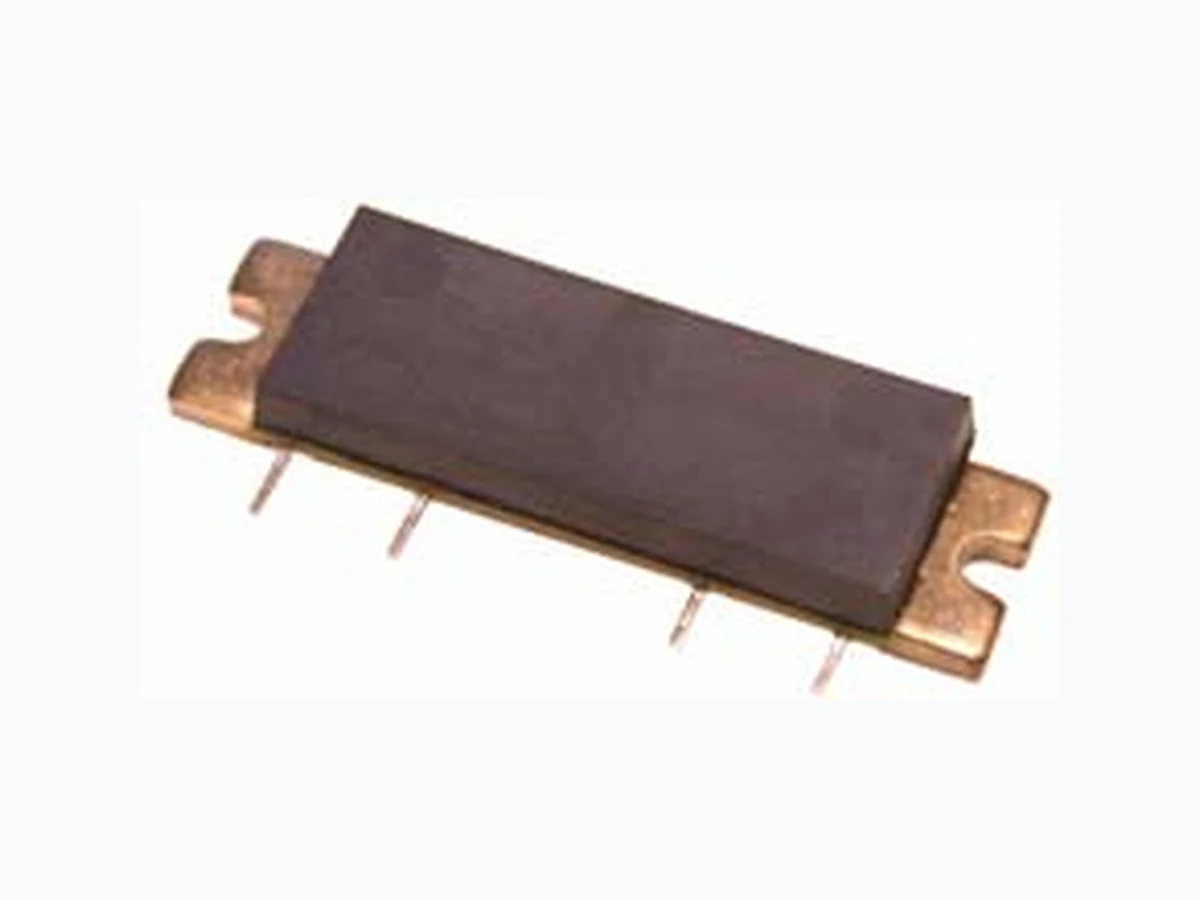
XD010-04S-D4F ETC1
Document overview
- Manufacturer or author: Provided By www.digicamel.com(FREE DATASHEET DOWNLOAD SITE)
- PDF pages: 4
Technical content
The information provided herein is believed to be reliable at press time. Sirenza Microdevices assumes no responsibility for inaccuracies or ommisions. Sirenza Microdevices assumes no responsibility for the use of this information, and all such information shall be entirely at the user’s own risk. Prices and specifications are subject to change without notice. No patent rights or licenses to any of the circuits described herein are implied or granted to any third party. Sirenza Microdevices does not authorize or warrant any Sirenza Microdevices product for use in life-support devices and/or systems. Copyright 2005 Sirenza Microdevices, Inc. All worldwide rights reserved. 303 S. Technology Court, Broomfield, CO 80021 Phone: (800) SMI-MMIC http://www.sirenza.com EDS-104259 Rev B Preliminary The XD010-04S-D4F 10W power module is a robust broadband 2-stage Class A/AB ampli- fier, suitable for use as a power amplifier driver or output stage. It is a drop-in, no-tune, solu- tion for high power applications requiring high efficiency, excellent linearity, and unit to unit repeatability. Internal bias current compensa- tion ensures stable performance over a wide temperature range. Key Specifications Parameter Test Conditions: Zin = Zout = 50Ω, VD = 28.0V, ID1 = 230mA, ID2 = 150mA, TFlange = 25ºC Unit Min. Typ. Max. Frequency Frequency of Operation MHz 350 600 P1dB Output Power at 1dB Compression, 450MHz W Gain Gain at 10W Output Power, 450MHz dB Gain Flatness Peak to Peak Gain Variation, 350 - 600MHz dB 1.0 2.0 IRL Input Return Loss 1W Output Power, 350 - 600MHz dB Efficiency Drain Efficiency at 10W CW, 350-600MHz Linearity 3rd Order IMD at 10W PEP (Two Tone), 450MHz & 451MHz dBc -32 -28 Delay Signal Delay from Pin 1 to Pin 4 nS 2.5 Phase Linearity Deviation from Linear Phase (Peak to Peak) Deg 0.5 Functional Block Diagram XD010-04S-D4F 350-600 MHz Class AB 10W Power Amplifier Module Product Features
Applications
- 50 W RF Impedance
- > 10W Output P1dB
- Single Voltage Operation
- High Gain: 32 dB Typical
- Temperature Compensation
- Robust 8000V ESD (HBM), Class 3B
- DTV
- Public Service
- Wireless Infrastructure
- Military
- CDMA or GSM Product Description Case Flange = Ground Stage 1 Stage 2 RF In RF Out VD1 V Quality Specifications Parameter Unit Min Typical Max ESD Rating Human Body Model, JEDEC Document - JESD22-A114-B V 8000 MTTF 85oC Baseplate, 200oC Channel H
1.2 X 10⁶
RTH, j-l Thermal Resistance Stage 1 (Junction to Case) ºC/W RTH, j-2 Thermal Resistance Stage 2 (Junction to Case) ºC/W
303 S. Technology Court, Broomfield, CO 80021 Phone: (800) SMI-MMIC http://www.sirenza.com EDS-104259 Rev B Preliminary XD010-04S-D4F 350-600 MHz 10W Amp Pin Description Pin # Function Comments RF Input Internally connected to DC ground. Do not apply DC voltages to the RF leads. VD1 1st stage bias VD2 2nd stage bias. Integrated temperature compensation maintains constant current over the operating tempera- ture range. See Note 1. RF Output Internally connected to DC ground. Do not apply DC voltages to the RF leads. Flange Gnd Baseplate provides electrical ground and a thermal transfer path for the device. Proper mounting assures opti- mal performance and the highest reliablility. See Sirenza applications note: AN-060 Installation Instructions for XD Module Series. Simplified Device Schematic Absolute Maximum Ratings Parameters Value Unit 1st Stage Bias Voltage (VD1 ) V 2nd Stage Bias Voltage (VD2) V RF Input Power +20 dBm Load VSWR for Continuous Operation With- out Damage 5:1 VSWR Device Channel Temperature +200 ºC Lead Temperature During Solder Reflow +210 ºC Operating Temperature Range -20 to +90 ºC Storage Temperature Range -40 to +100 ºC Operation of this device beyond any one of these limits may cause permanent damage. For reliable continuous operation refer to the key specifications table on the first page of the datasheet. Caution: ESD Sensitive Appropriate precautions in handling, packag- ing and testing devices must be observed. Note 1: The internally generated gate voltage is ther- mally compensated to maintain constant drain quiescent current over the temperature range listed in the data sheet. No compensation is provided for gain changes with temperature. This can only be provided with an external AGC circuit. Note 2: Internal RF decoupling is included on all bias leads. No additional bypass elements are required, however some applications may require energy storage on the VD leads to accommodate modulated signals. V VD2 Temperature Compensation RF in Bias Network RF out Case Flange = Ground
303 S. Technology Court, Broomfield, CO 80021 Phone: (800) SMI-MMIC http://www.sirenza.com EDS-104259 Rev B Preliminary XD010-04S-D4F 350-600 MHz 10W Amp Test Board Schematic with module attachments shown Test Board Layout and Bill of Materials Component
Description
Rogers 4350, er=3.5 Thickness=30mils Rogers J1, J2 SMA, RF, PCB Mount Tab W / Flange Johnson MTA Post Header, 6 Pin, Rectangle, Polarized, Surface Mount AMP C1, C2 Cap, 10mF 50V, 10%, Tant, D Kemet C4, C6 Cap, 0.01mF, 100V, 10%, 1206 Johanson C3, C5 Cap, 1000pF, 100V, 10%, 1206 Johanson Mounting Screws 4-40 X 0.250” Various Gerber files, DXF drawings, a detailed BOM, and assembly recommendations for the test board with fixture are available from Sirenza applications.
www.digicamel.com Copyright © Each Manufacturing Company. All Datasheets cannot be modified without permission. This datasheet has been download from : www.digicamel.com 100% Free DataSheet Search Site. Free Download. No Register. Fast Search System. www.digicamel.com