


 Download PDF
X40010 XICOR
Document overview
- PDF pages: 25
Technical content
Page 1
New Features
- Monitor Voltages: 5V to 0.9V
Preliminary Datasheet
- Independent Core Voltage Monitor

FEATURES
- Dual voltage detection and reset assertion —Standard reset threshold settings See Selection table on page 2.
—Adjust low voltage reset threshold voltages using special programming sequence —Reset signal valid to V = 1V
CC
—Monitor three voltages or detect power fail
- Independent Core Voltage Monitor (V2MON)
- Fault detection register
- Selectable power on reset timeout (0.05s, 0.2s, 0.4s, 0.8s)
- Selectable watchdog timer interval (25ms, 200ms, 1.4s, off)
- Low power CMOS —25µA typical standby current, watchdog on —6µA typical standby current, watchdog off
- 400kHz 2-wire interface
- 2.7V to 5.5V power supply operation
- Available packages —8-lead SOIC, TSSOP
APPLICATIONS
- Communication Equipment —Routers, Hubs, Switches —Disk Arrays, Network Storage
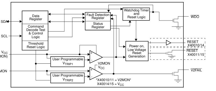
BLOCK DIAGRAM
- Industrial Systems —Process Control —Intelligent Instrumentation
- Computer Systems —Computers —Network Servers
DESCRIPTION
The X40010/11/14/15 combines power-on reset control, watchdog timer, supply voltage supervision, and secondary voltage supervision, in one package. This combination lowers system cost, reduces board space requirements, and increases reliability. Applying voltage to V activates the power on reset
CC
circuit which holds RESET/RESET active for a period of time. This allows the power supply and system oscillator to stabilize before the processor can execute code. Low V detection circuitry protects the user’s system CC from low voltage conditions, resetting the system when V falls below the minimum V
point. RESET/
CC
TRIP1
RESET is active until V returns to proper operating
CC
level and stabilizes. A second voltage monitor circuit tracks the unregulated supply to provide a power fail warning or monitors different power supply voltage. Three common low voltage combinations are available, however, Xicor’s unique circuits allows the
(V1MON)
V2MON
Characteristics subject to change without notice.1 of 25
Page 2
threshold for either voltage monitor to be repro-
The device features a 2-wire interface and software
2 ®
grammed to meet special needs or to fine-tune the
protocol allowing operation on an I C bus.
threshold for applications requiring higher precision. The Watchdog Timer provides an independent protection mechanism for microcontrollers. When the microcontroller fails to restart a timer within a selectable time out interval, the device activates the WDO signal. The user selects the interval from three preset values. Once selected, the interval does not change, even after cycling the power.
Dual Voltage Monitors
| Device | Expected System Voltages | Vtrip1(V) | Vtrip2(V) | POR (system) | ||
| X40010/11 -A -B -C | 5V; 3V or 3.3V 5V; 3V 3V; 3.3V; 1.8V | 2.0–4.75* 4.55–4.65* 4.35–4.45* 2.85–2.95* | 1.70–4.75 2.85–2.95 2.55–2.65 1.65–1.75 | RESET = X40010 RESET = X40011 | ||
| X40014/15 -A -B -C | 3V; 3.3V; 1.5V 3V; 1.5V 3V or 3.3V; 1.1 or 1.2V | 2.0–4.75* 2.85–2.95* 2.55–2.65* 2.85–2.95* | 0.90–3.50* 1.25–1.35* 1.25–1.35* 0.95–1.05* | RESET = X40014 RESET = X40015 | ||
| *Voltage monitor requires VCC to operation. Others are independent of VCC. PIN CONFIGURATION | ||||||
| X40010/14, X40011/15 X40010/14, X40011/15 8-Pin SOIC 8-Pin TSSOP V2FAIL 1 8 VCC WDO 1 8 SCL V2MON 2 7 WDO VCC 2 7 SDA RESET/RESET 3 6 SCL V2FAIL 3 6 VSS VSS 4 5 SDA V2MON 4 5 RESET/RESET | ||||||
| PIN DESCRIPTION | ||||||
| Pin | Name | Function | ||||
| SOIC | TSSOP | |||||
| 1 | 3 | V2FAIL | V2 Voltage Fail Output. This open drain output goes LOW when V2MON is less than V and TRIP2 goes HIGH when V2MON exceeds V . There is no power up reset delay circuitry on this pin. TRIP2 | |||
| 2 | 4 | V2MON | V2 Voltage Monitor Input. When the V2MON input is less than the V voltage, V2FAIL goes TRIP2 LOW. This input can monitor an unregulated power supply with an external resistor divider or can monitor a second power supply with no external components. Connect V2MON to V or V SS CC when not used.The V2MON comparator is supplied by V2MON (X40010/11) or by V Input CC (X40014/15). | |||
| 3 | 5 | RESET/ RESET | RESET Output. (X40011/15) This is an active LOW, open drain output which goes active when- ever V falls below V . It will remain active until V rises above V and for the t CC TRIP1 CC TRIP1 PURST thereafter. RESET Output. (X40010/14) This is an active HIGH CMOS output which goes active whenever V falls below V . It will remain active until V rises above V and for the t there- CC TRIP1 CC TRIP1 PURST after. | |||
| 4 | 6 | V SS | Ground | |||
Characteristics subject to change without notice.2 of 25
Page 3
PIN DESCRIPTION
(Continued)
| Pin | Name | Function | |
| SOIC | TSSOP | ||
| 5 | 7 | SDA | Serial Data. SDA is a bidirectional pin used to transfer data into and out of the device. It has an open drain output and may be wire ORed with other open drain or open collector outputs. This pin requires a pull up resistor and the input buffer is always active (not gated). Watchdog Input. A HIGH to LOW transition on the SDA (while SCL is toggled from HIGH to LOW and followed by a stop condition) restarts the Watchdog timer. The absence of this tran- sition within the watchdog time out period results in WDO going active. |
| 6 | 8 | SCL | Serial Clock. The Serial Clock controls the serial bus timing for data input and output. |
| 7 | 1 | WDO | WDO Output. WDO is an active LOW, open drain output which goes active whenever the watchdog timer goes active. |
| 8 | 2 | V CC | Supply Voltage |
PRINCIPLES OF OPERATION
Power On Reset Application of power to the X40010/11/14/15 activates a Power On Reset Circuit that pulls the RESET/RESET pins active. This signal provides several benefits. – It prevents the system microprocessor from starting to operate with insufficient voltage. – It prevents the processor from operating prior to stabilization of the oscillator. – It allows time for an FPGA to download its configuration prior to initialization of the circuit. – It prevents communication to the EEPROM, greatly reducing the likelihood of data corruption on power up. When V exceeds the device V
threshold value for
CC
TRIP1
t (selectable) the circuit releases the RESET PURST (X40011) and RESET (X40010) pin allowing the system to begin operation.
Low Voltage V (V1 Monitoring)
CC
During operation, the X40010/11/14/15 monitors the VCC level and asserts RESET/RESET if supply voltage falls
. The RESET/RESET
below a preset minimum V
TRIP1
signal prevents the microprocessor from operating in a power fail or brownout condition. The V1FAIL signal remains active until the voltage drops below 1V. It also remains active until V returns and exceeds V
for
CC
TRIP1
. t PURST
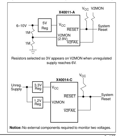
Low Voltage V2 Monitoring The X40010/11/14/15 also monitors a second voltage level and asserts V2FAIL if the voltage falls below a preset minimum V
. The V2FAIL signal is either TRIP2
ORed with RESET to prevent the microprocessor from operating in a power fail or brownout condition or used to interrupt the microprocessor with notification of an
impending power failure. For the X40010/11 the V2FAIL signal remains active until the V drops below 1V (V
CC
CC
falling). It also remains active until V2MON returns and exceeds V
by 0.2V. This voltage sense circuitry TRIP2 monitors the power supply connected to the V2MON pin. If V = 0, V2MON can still be monitored. CC For the X40014/15 devices, the V2FAIL signal remains actice until V drops below 1Vx and remains active until
CC
V2MON returns and exceeds V
. This sense circuitry TRIP2
is powered by V . If V = 0, V2MON cannot be moni-
CC CC
tored.
Figure 1. Two Uses of Multiple Voltage Monitoring
Characteristics subject to change without notice.3 of 25
Page 4
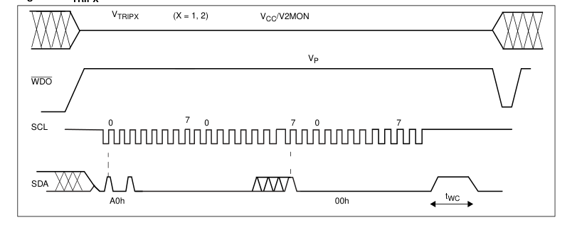
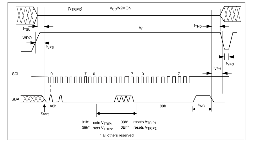
Figure 2. V
Set/Reset Conditions
TRIPX
WATCHDOG TIMER
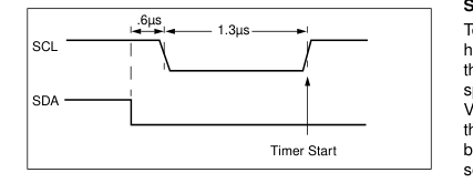
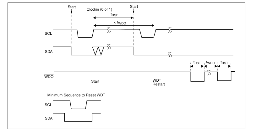
The Watchdog Timer circuit monitors the microprocessor activity by monitoring the SDA and SCL pins. The microprocessor must toggle the SDA pin HIGH to LOW periodically, while SCL also toggles from HIGH to LOW (this is a start bit) followed by a stop condition prior to the expiration of the watchdog time out period to prevent a WDO signal going active. The state of two nonvolatile control bits in the Status Register determines the watchdog timer period. The microprocessor can change these watchdog bits by writing to the X40010/ 11/14/15 control register (also refer to page 19).
Figure 3. Watchdog Restart
V1 AND V2 THRESHOLD PROGRAM PROCEDURE
(OPTIONAL)
The X40010/11/14/15is shipped with standard V1 and V2 threshold (V
V ) voltages. These values
TRIP1, TRIP2
will not change over normal operating and storage conditions. However, in applications where the standard thresholds are not exactly right, or if higher precision is needed in the threshold value, the X40010/11/14/15trip
points may be adjusted. The procedure is described below, and uses the application of a high voltage control signal.
Setting a V
Voltage (x=1, 2) TRIPx
There are two procedures used to set the threshold voltages (V
), depending if the threshold voltage to TRIPx be stored is higher or lower than the present value. For example, if the present V
is 2.9 V and the new TRIPx
is 3.2 V, the new voltage can be stored directly V TRIPx into the V
cell. If however, the new setting is to be TRIPx lower than the present setting, then it is necessary to “reset” the V
voltage before setting the new value. TRIPx
Setting a Higher V
Voltage (x=1, 2) TRIPx
To set a V
threshold to a new voltage which is TRIPx higher than the present threshold, the user must apply the desired V
threshold voltage to the corre- TRIPx
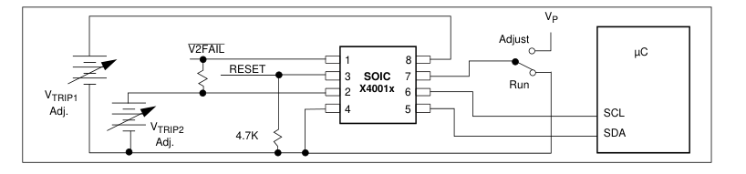
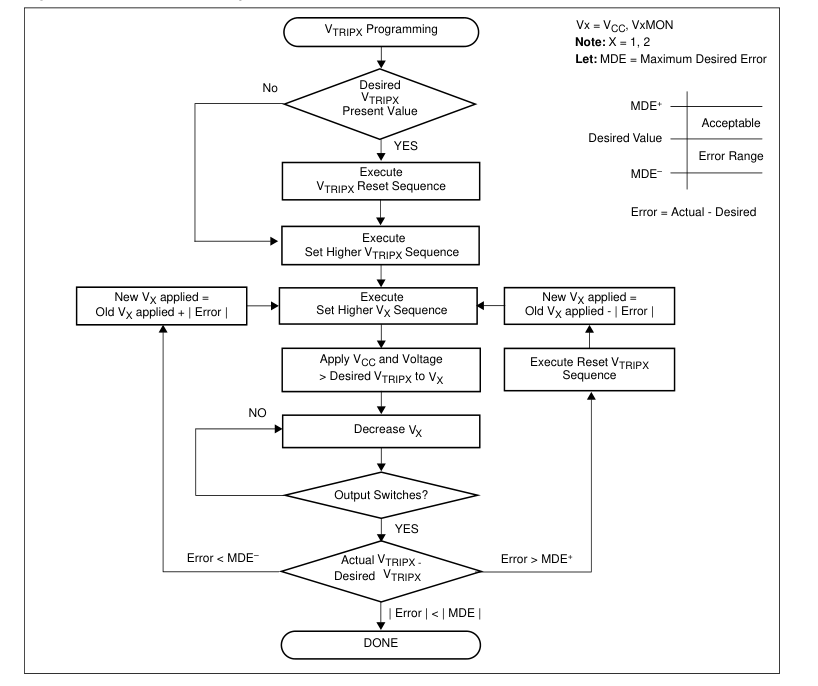
sponding input pin Vcc(V1MON), or V2MON. The Vcc(V1MON) and V2MON must be tied together during this sequence. Then, a programming voltage (Vp) must be applied to the WDO pin before a START condition is set up on SDA. Next, issue on the SDA pin the Slave Address A0h, followed by the Byte Address 01h for and 09h for V
, and a 00h Data Byte in
V TRIP1
TRIP2
order to program VTRIPx. The STOP bit following a valid write operation initiates the programming sequence. Pin WDO must then be brought LOW to complete the operation. Note: This operation does not corrupt the memory array.
Characteristics subject to change without notice.4 of 25
Page 5
Setting a Lower VTRIPx Voltage (x=1, 2) In order to set VTRIPx to a lower voltage than the present value, then VTRIPx must first be “reset” according to the procedure described below. Once VTRIPx has been “reset”, then VTRIPx can be set to the desired voltage using the procedure described in “Setting a Higher VTRIPx Voltage”.
Resetting the VTRIPx Voltage To reset a VTRIPx voltage, apply the programming voltage (Vp) to the WDO pin before a START condition is set up on SDA. Next, issue on the SDA pin the Slave Address A0h followed by the Byte Address 03h for VTRIP1 and 0Bh for VTRIP2, followed by 00h for the Data Byte in order to reset VTRIPx. The STOP bit following a valid write operation initiates the programming sequence. Pin WDO must then be brought LOW to complete the operation. After being reset, the value of VTRIPx becomes a nominal value of 1.7V or lesser. Note: This operation does not corrupt the memory array.
CONTROL REGISTER
The Control Register provides the user a mechanism for changing the Block Lock and Watchdog Timer settings. The Block Lock and Watchdog Timer bits are nonvolatile and do not change when power is removed.
Figure 4. Sample VTRIP Reset Circuit
The Control Register is accessed with a special preamble in the slave byte (1011) and is located at address 1FFh. It can only be modified by performing a byte write operation directly to the address of the register and only one data byte is allowed for each register write operation. Prior to writing to the Control Register, the WEL and RWEL bits must be set using a two step process, with the whole sequence requiring 3 steps. See "Writing to the Control Registers" on page 7. The user must issue a stop, after sending this byte to the register, to initiate the nonvolatile cycle that stores WD1, WD0, PUP1, PUP0, BP1, and BP0. The X40010/ 11/14/15 will not acknowledge any data bytes written
after the first byte is entered. The state of the Control Register can be read at any time by performing a random read at address 01Fh, using the special preamble. Only one byte is read by each register read operation. The master should supply a stop condition to be consistent with the bus protocol, but a stop is not required to end this operation.
| 7 | 6 | 5 | 4 | 3 | 2 | 1 | 0 |
| PUP1 | WD1 | WD0 | BP | 0 | RWEL | WEL | PUP0 |
RWEL: Register Write Enable Latch (Volatile) The RWEL bit must be set to “1” prior to a write to the Control Register.
Characteristics subject to change without notice. 5 of 25
Page 6
Figure 5. VTRIPX Set/Reset Sequence (X = 1, 2)
WEL: Write Enable Latch (Volatile) The WEL bit controls the access to the memory and to
the Register during a write operation. This bit is a vola-
tile latch that powers up in the LOW (disabled) state.
While the WEL bit is LOW, writes to any address,
including any control registers will be ignored (no
acknowledge will be issued after the Data Byte). The
WEL bit is set by writing a “1” to the WEL bit and zeros
to the other bits of the control register.
Once set, WEL remains set until either it is reset to 0
(by writing a “0” to the WEL bit and zeros to the other
bits of the control register) or until the part powers up
again. Writes to the WEL bit do not cause a high volt-
age write cycle, so the device is ready for the next
operation immediately after the stop condition.
Characteristics subject to change without notice. 6 of 25
Page 7
PUP1, PUP0: Power Up Bits (Nonvolatile) The Power Up bits, PUP1 and PUP0, determine the tPURST time delay. The nominal power up times are shown in the following table.
| PUP1 | PUP0 | Power on Reset Delay (t ) PURST |
| 0 | 0 | 50ms |
| 0 | 1 | 200ms (factory setting) |
| 1 | 0 | 400ms |
| 1 | 1 | 800ms |
| WD1, WD0: Watchdog Timer Bits (Nonvolatile) The bits WD1 and WD0 control the period of the Watchdog Timer. The options are shown below. | ||
| WD1 | WD0 | Watchdog Time Out Period |
| 0 | 0 | 1.4 seconds |
| 0 | 1 | 200 milliseconds |
| 1 | 0 | 25 milliseconds |
| 1 | 1 | disabled (factory setting) |
Writing to the Control Registers Changing any of the nonvolatile bits of the control and trickle registers requires the following steps: – Write a 02H to the Control Register to set the Write Enable Latch (WEL). This is a volatile operation, so there is no delay after the write. (Operation preceded by a start and ended with a stop). – Write a 06H to the Control Register to set the Register Write Enable Latch (RWEL) and the WEL bit. This is also a volatile cycle. The zeros in the data byte are required. (Operation proceeded by a start and ended with a stop). – Write a one byte value to the Control Register that has all the control bits set to the desired state. The
Control register can be represented as qxys 001r in binary, where xy are the WD bits, s isthe BP bit and qr are the power up bits. This operation proceeded by a start and ended with a stop bit. Since this is a
nonvolatile write cycle it will take up to 10ms to complete. The RWEL bit is reset by this cycle and the sequence must be repeated to change the nonvolatile bits again. If bit 2 is set to ‘1’ in this third step (qxys 011r) then the RWEL bit is set, but the WD1, WD0, PUP1, PUP0, and BP bits remain unchanged. Writing a second byte to the control register is not allowed. Doing so aborts the write operation and returns a NACK. – A read operation occurring between any of the previous operations will not interrupt the register write operation. – The RWEL bit cannot be reset without writing to the nonvolatile control bits in the control register, power cycling the device or attempting a write to a write
protected block. To illustrate, a sequence of writes to the device consisting of [02H, 06H, 02H] will reset all of the nonvolatile bits in the Control Register to 0. A sequence of [02H, 06H, 06H] will leave the nonvolatile bits unchanged and the RWEL bit remains set.
FAULT DETECTION REGISTER
The Fault Detection Register (FDR) provides the user the status of what causes the system reset active. The Manual Reset Fail, Watchdog Timer Fail and three Low Voltage Fail bits are volatile.
| 7 | 6 | 5 | 4 | 3 | 2 | 1 | 0 |
| LV1F | LV2F | 0 | WDF | 0 | 0 | 0 | 0 |
The FDR is accessed with a special preamble in the slave byte (1011) and is located at address 0FFh. It can only be modified by performing a byte write operation directly to the address of the register and only one data byte is allowed for each register write operation. There is no need to set the WEL or RWEL in the control register to access this fault detection register.
Characteristics subject to change without notice. 7 of 25
Page 8
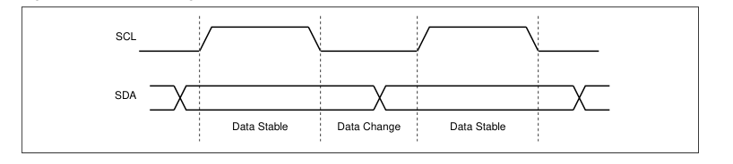
Figure 6. Valid Data Changes on the SDA Bus
At power-up, the Fault Detection Register is defaulted to all “0”. The system needs to initialize this register to all “1” before the actual monitoring take place. In the event of any one of the monitored sources failed. The corresponding bits in the register will change from a “1” to a “0” to indicate the failure. At this moment, the system should perform a read to the register and noted the cause of the reset. After reading the register the system should reset the register back to all “1” again. The state of the Fault Detection Register can be read at any time by performing a random read at address 0FFh, using the special preamble. The FDR can be read by performing a random read at
OFFh address of the register at any time. Only one byte of data is read by the register read operation.
WDF, Watchdog Timer Fail Bit (Volatile) The WDF bit will set to “0” when the WDO goes active.
LV1F, Low VCC Reset Fail Bit (Volatile) The LV1F bit will be set to “0” when VCC (V1MON) falls below VTRIP1.
LV2F, Low V2MON Reset Fail Bit (Volatile) The LV2F bit will be set to “0” when V2MON falls below VTRIP2.
SERIAL INTERFACE
Interface Conventions The device supports a bidirectional bus oriented protocol. The protocol defines any device that sends data onto the bus as a transmitter, and the receiving device as the receiver. The device controlling the transfer is called the master and the device being controlled is called the slave. The master always initiates data transfers, and provides the clock for both transmit and receive operations. Therefore, the devices in this family operate as slaves in all applications.
Serial Clock and Data Data states on the SDA line can change only during SCL LOW. SDA state changes during SCL HIGH are reserved for indicating start and stop conditions. See Figure 6.
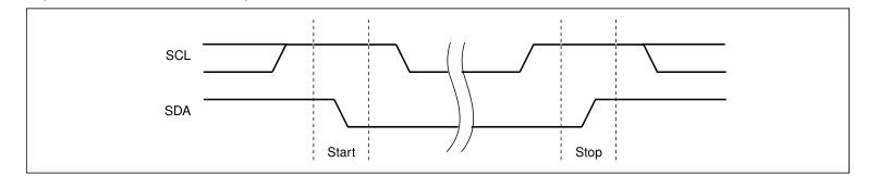
Serial Start Condition All commands are preceded by the start condition, which is a HIGH to LOW transition of SDA when SCL is HIGH. The device continuously monitors the SDA and SCL lines for the start condition and will not respond to any command until this condition has been met. See Figure 6.
Serial Stop Condition All communications must be terminated by a stop condition, which is a LOW to HIGH transition of SDA when SCL is HIGH. The stop condition is also used to place the device into the Standby power mode after a read sequence. A stop condition can only be issued after the transmitting device has released the bus. See Figure 6.
Characteristics subject to change without notice. 8 of 25
Page 9
Figure 7. Valid Start and Stop Conditions
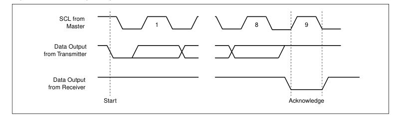
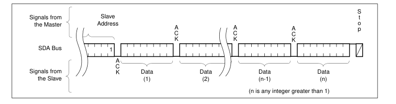
Serial Acknowledge Acknowledge is a software convention used to indicate successful data transfer. The transmitting device, either master or slave, will release the bus after transmitting eight bits. During the ninth clock cycle, the receiver will pull the SDA line LOW to acknowledge that it received the eight bits of data. See Figure 8. The device will respond with an acknowledge after recognition of a start condition and if the correct Device Identifier and Select bits are contained in the Slave Address Byte. If a write operation is selected, the device will respond with an acknowledge after the receipt of each subsequent eight bit word. The device will acknowledge all incoming data and address bytes,
except for the Slave Address Byte when the Device Identifier and/or Select bits are incorrect. In the read mode, the device will transmit eight bits of data, release the SDA line, then monitor the line for an acknowledge. If an acknowledge is detected and no stop condition is generated by the master, the device will continue to transmit data. The device will terminate further data transmissions if an acknowledge is not
Figure 8. Acknowledge Response From Receiver
detected. The master must then issue a stop condition to return the device to Standby mode and place the device into a known state.
Serial Write Operations
Byte Write For a write operation, the device requires the Slave Address Byte and a Word Address Byte. This gives the master access to any one of the words in the array. After receipt of the Word Address Byte, the device responds with an acknowledge, and awaits the next eight bits of data. After receiving the 8 bits of the Data Byte, the device again responds with an acknowledge. The master then terminates the transfer by generating a stop condition, at which time the device begins the internal write cycle to the nonvolatile memory. During this internal write cycle, the device inputs are disabled, so the device will not respond to any requests from the mas-
ter. The SDA output is at high impedance. See Figure 9. A write to a protected block of memory will suppress the acknowledge bit.
Characteristics subject to change without notice. 9 of 25
Page 10
Read Operation Prior to issuing the Slave Address Byte with the R/W bit set to one, the master must first perform a “dummy” write operation. The master issues the start condition and the Slave Address Byte, receives an acknowledge, then issues the Word Address Bytes. After acknowledging receipts of the Word Address Bytes, the master immedi-
Figure 9. Read Sequence
ately issues another start condition and the Slave Address Byte with the R/W bit set to one. This is followed by an acknowledge from the device and then by the eight bit word. The master terminates the read operation by not responding with an acknowledge and then issuing a stop condition. See Figure 12 for the address, acknowledge, and data transfer sequence.
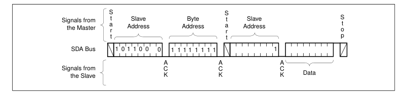
Stops and Write Modes Stop conditions that terminate write operations must be sent by the master after sending at least 1 full data byte plus the subsequent ACK signal. If a stop is issued in the middle of a data byte, or before 1 full data byte plus its associated ACK is sent, then the device will reset itself without performing the write. The contents of the array will not be effected.
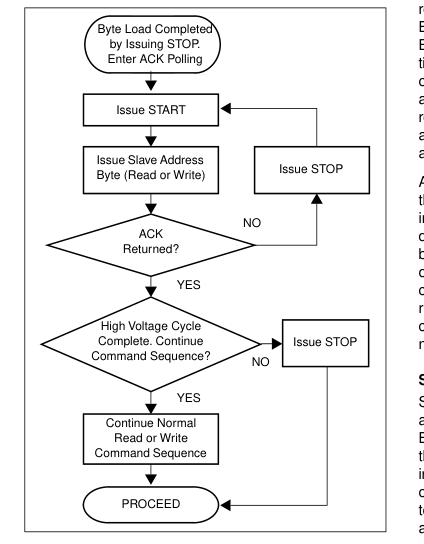
Acknowledge Polling The disabling of the inputs during high voltage cycles can be used to take advantage of the typical 5ms write cycle time. Once the stop condition is issued to indicate the end of the master’s byte load operation, the device initiates the internal high voltage cycle. Acknowledge polling can be initiated immediately. To do this, the master issues a start condition followed by the Slave Address Byte for a write or read operation. If the device is still busy with the high voltage cycle then no ACK will be returned. If the device has completed the write operation, an ACK will be returned and the host can then proceed with the read or write operation. See Figure
12.
Serial Read Operations Read operations are initiated in the same manner as write operations with the exception that the R/W bit of the Slave Address Byte is set to one. There are three basic read operations: Current Address Reads, Random Reads, and Sequential Reads.
Current Address Read Internally the device contains an address counter that maintains the address of the last word read incremented by one. Therefore, if the last read was to address n, the next read operation would access data from address n+1. On power up, the address of the address counter is undefined, requiring a read or write operation for initialization. Upon receipt of the Slave Address Byte with the R/W bit set to one, the device issues an acknowledge and then transmits the eight bits of the Data Byte. The master terminates the read operation when it does not respond with an acknowledge during the ninth clock and then issues a stop condition. See Figure 13 for the
address, acknowledge, and data transfer sequence.
Characteristics subject to change without notice. 10 of 25
Page 11
Figure 10. Acknowledge Polling Sequence
It should be noted that the ninth clock cycle of the read operation is not a “don’t care.” To terminate a read operation, the master must either issue a stop condition during the ninth cycle or hold SDA HIGH during the ninth clock cycle and then issue a stop condition.
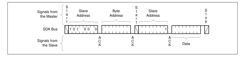
Random Read Random read operation allows the master to access any memory location in the array. Prior to issuing the Slave Address Byte with the R/W bit set to one, the master must first perform a “dummy” write operation. The master
issues the start condition and the Slave Address Byte, receives an acknowledge, then issues the Word Address Bytes. After acknowledging receipts of the Word Address Bytes, the master immediately issues another start condition and the Slave Address Byte with the R/W bit set to one. This is followed by an acknowledge from the device and then by the eight bit word. The master terminates the read operation by not responding with an acknowledge and then issuing a stop condition. See Figure 14 for the address, acknowledge, and data transfer sequence. A similar operation called “Set Current Address” where the device will perform this operation if a stop is issued
instead of the second start shown in Figure 13. The device will go into standby mode after the stop and all bus activity will be ignored until a start is detected. This operation loads the new address into the address counter. The next Current Address Read operation will read from the newly loaded address. This operation could be useful if the master knows the next address it needs to read, but is not ready for the data.
Sequential Read Sequential reads can be initiated as either a current address read or random address read. The first Data Byte is transmitted as with the other modes; however, the master now responds with an acknowledge, indicating it requires additional data. The device continues to output data for each acknowledge received. The master terminates the read operation by not responding with an acknowledge and then issuing a stop condition. The data output is sequential, with the data from address n followed by the data from address n + 1. The address counter for read operations increments through all page and column addresses, allowing the entire memory contents to be serially read during one opera-
tion. At the end of the address space the counter “rolls over” to address 0000H and the device continues to output data for each acknowledge received. See Figure 15 for the acknowledge and data transfer sequence.
Characteristics subject to change without notice. 11 of 25
Page 12
SERIAL DEVICE ADDRESSING
Memory Address Map CR, Control Register, CR7: CR0 Address: 1FFhex FDR, Fault DetectionRegister, FDR7: FDR0 Address: 0FFhex
Slave Address Byte Following a start condition, the master must output a Slave Address Byte. This byte consists of several parts: – a device type identifier that is always ‘101x’. Where x=0 is for Array, x=1 is for Control Register or Fault Detection Register. – next two bits are ‘0’. – next bit that becomes the MSB of the address.
Figure 12. Current Address Read Sequence
Figure 11. X40010/11/14/15 Addressing
Slave Byte
Control Register
| 1 | 0 | 1 | 1 | 0 | 0 | 1 | R/W |
| 1 | 0 | 1 | 1 | 0 | 0 | 0 | R/W |
Fault Detection Register
Word Address
Control Register
| 1 | 1 | 1 | 1 | 1 | 1 | 1 | 1 |
| 1 | 1 | 1 | 1 | 1 | 1 | 1 | 1 |
Fault Detection Register

Figure 13. Random Address Read Sequence
Characteristics subject to change without notice. 12 of 25
Page 13
– One bit of the slave command byte is a R/W bit. The R/W bit of the Slave Address Byte defines the operation to be performed. When the R/W bit is a one, then a read operation is selected. A zero selects a write operation.
Word Address The word address is either supplied by the master or obtained from an internal counter. The internal counter is undefined on a power up condition.
Operational Notes The device powers-up in the following state: – The device is in the low power standby state. – The WEL bit is set to ‘0’. In this state it is not possible to write to the device. – SDA pin is the input mode. – RESET/RESET Signal is active for tPURST.
Figure 14. Sequential Read Sequence
Data Protection The following circuitry has been included to prevent inadvertent writes: – The WEL bit must be set to allow write operations. – The proper clock count and bit sequence is required prior to the stop bit in order to start a nonvolatile write cycle. – A three step sequence is required before writing into the Control Register to change Watchdog Timer or Block Lock settings.
Characteristics subject to change without notice. 13 of 25
Page 14
ABSOLUTE MAXIMUM RATINGS
Temperature under bias ................... –65°C to +135°C Storage temperature ........................ –65°C to +150°C Voltage on any pin with respect to VSS......................................–1.0V to +7V D.C. output current ............................................... 5mA Lead temperature (soldering, 10 seconds)........ 300°C
RECOMMENDED OPERATING CONDITIONS
| Temperature | Min. | Max. |
|---|---|---|
| Commercial | 0°C | 70°C |
| Industrial | –40°C | +85°C |
D.C. OPERATING CHARACTERISTICS
COMMENT
Stresses above those listed under “Absolute Maximum Ratings” may cause permanent damage to the device. This is a stress rating only; functional operation of the device (at these or any other conditions above those listed in the operational sections of this specification) is not implied. Exposure to absolute maximum rating conditions for extended periods may affect device reliability.
| Version | Chip Supply Voltage | Monitored* Voltages |
| X40010/11 -A or -B | 2.7V to 5.5V | 2.6V to 5V |
| X40010/11- C, X40014/15 | 2.7V to 5.5V | 1V to 3.6V |
\*See Ordering Info
(Over the recommended operating conditions unless otherwise specified)
| Symbol | Parameter | Min. | Typ.(4) | Max. | Unit | Test Conditions |
|---|---|---|---|---|---|---|
| I (1) CC1 | Active Supply Current (V ) Read CC | 1.5 | mA | V = V x 0.1 IL CC V = V x 0.9, IH CC f = 400kHz SCL | ||
| I (1) CC2 | Active Supply Current (V ) Read CC | 3.0 | mA | |||
| I (1)(6) SB1 | Standby Current (V ) AC (WDT off) CC | 6 | 10 | µA | V = V x 0.1 IL CC VIH = V x 0.9 CC f , f = 400kHz SCL SDA | |
| I (2)(6) SB2 | Standby Current (V ) DC (WDT on) CC | 25 | 30 | µA | V = V = V SDA SCL CC Others = GND or V CC | |
| I LI | Input Leakage Current (SCL) | 10 | µA | V = GND to V IL CC | ||
| I LO | Output Leakage Current (SDA, V2FAIL, WDO, RESET) | 10 | µA | V = GND to V SDA CC Device is in Standby(2) | ||
| V (3) IL | Input LOW Voltage (SDA, SCL) | -0.5 | V x 0.3 CC | V | ||
| V (3) IH | Input HIGH Voltage (SDA, SCL) | V x 0.7 CC | V + 0.5 CC | V | ||
| V (6) HYS | Schmitt Trigger Input Hysteresis • Fixed input level • V related level CC | 0.2 .05 x V CC | V V | |||
| V OL | Output LOW Voltage (SDA, RESET/ RESET, V2FAIL, WDO) | 0.4 | V | I = 3.0mA (2.7–5.5V) OL I = 1.8mA (2.7–3.6V) OL | ||
| V OH | Output (RESET) HIGH Voltage | V – 0.8 CC V – 0.4 CC | V | I = -1.0mA (2.7–5.5V) OH I = -0.4mA (2.7–3.6V) OH |
Characteristics subject to change without notice. 14 of 25
Page 15
D.C. OPERATING CHARACTERISTICS (Continued) (Over the recommended operating conditions unless otherwise specified)
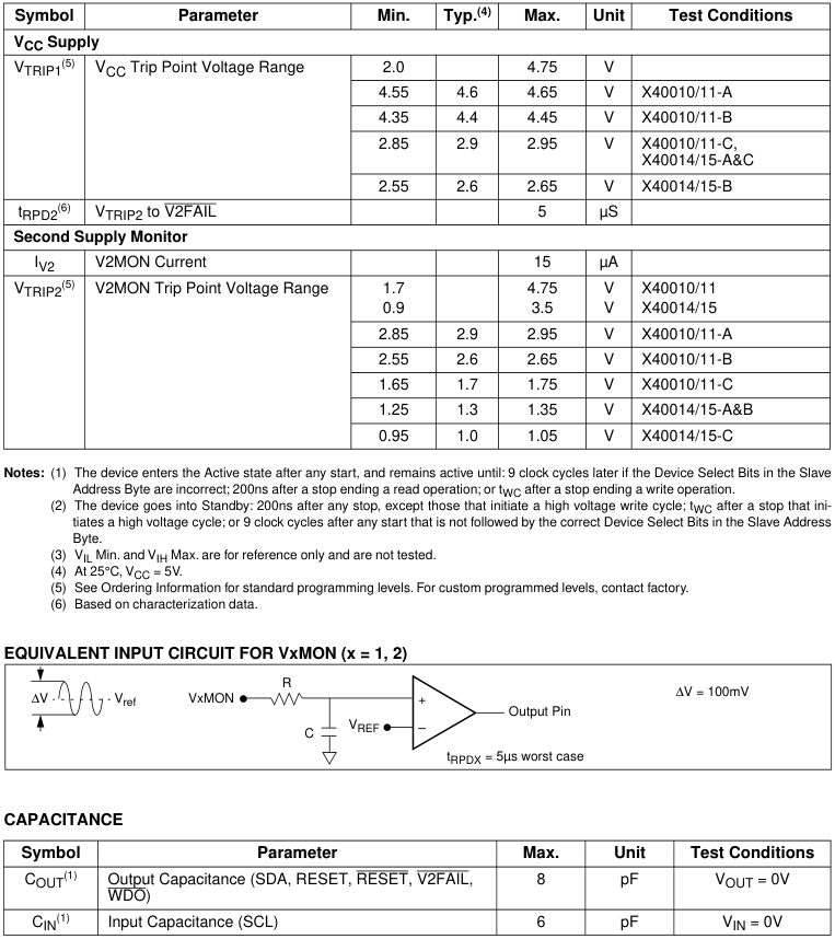
Note: (1) This parameter is not 100% tested.
Characteristics subject to change without notice. 15 of 25
Page 16
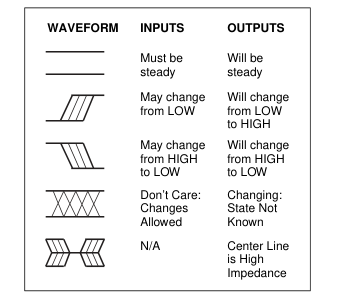
SYMBOL TABLE
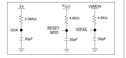
EQUIVALENT A.C. OUTPUT LOAD CIRCUIT FOR
VCC = 5V
A.C. TEST CONDITIONS
| Input pulse levels | V x 0.1 to V x 0.9 CC CC |
| Input rise and fall times | 10ns |
| Input and output timing levels | V x 0.5 CC |
| Output load | Standard output load |
Characteristics subject to change without notice. 16 of 25
Page 17
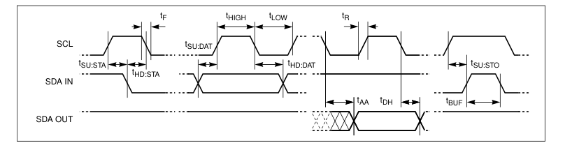
A.C. CHARACTERISTICS
| Symbol | Parameter | 400kHz | Unit | |
|---|---|---|---|---|
| Min. | Max. | |||
| f SCL | SCL Clock Frequency | 0 | 400 | kHz |
| t IN | Pulse width Suppression Time at inputs | 50 | ns | |
| t AA | SCL LOW to SDA Data Out Valid | 0.1 | 0.9 | µs |
| t BUF | Time the bus free before start of new transmission | 1.3 | µs | |
| t LOW | Clock LOW Time | 1.3 | µs | |
| t HIGH | Clock HIGH Time | 0.6 | µs | |
| t SU:STA | Start Condition Setup Time | 0.6 | µs | |
| t HD:STA | Start Condition Hold Time | 0.6 | µs | |
| t SU:DAT | Data In Setup Time | 100 | ns | |
| t HD:DAT | Data In Hold Time | 0 | µs | |
| t SU:STO | Stop Condition Setup Time | 0.6 | µs | |
| t DH | Data Output Hold Time | 50 | ns | |
| t R | SDA and SCL Rise Time | 20 +.1Cb(1) | 300 | ns |
| t F | SDA and SCL Fall Time | 20 +.1Cb(1) | 300 | ns |
| Cb | Capacitive load for each bus line | 400 | pF | |
Note: (1) Cb = total capacitance of one bus line in pF.
TIMING DIAGRAMS
Bus Timing
Characteristics subject to change without notice. 17 of 25
Page 18
Write Cycle Timing
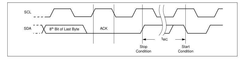
Nonvolatile Write Cycle Timing
| Symbol | Parameter | Min. | Typ.(1) | Max. | Unit |
|---|---|---|---|---|---|
| t (1) WC | Write Cycle Time | 5 | 10 | ms |
Note: (1) tWC is the time from a valid stop condition at the end of a write sequence to the end of the self-timed internal nonvolatile write cycle. It is the minimum cycle time to be allowed for any nonvolatile write by the user, unless Acknowledge Polling is used.
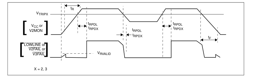
Power Fail Timings
Characteristics subject to change without notice. 18 of 25
Page 19
RESET/RESET Timings
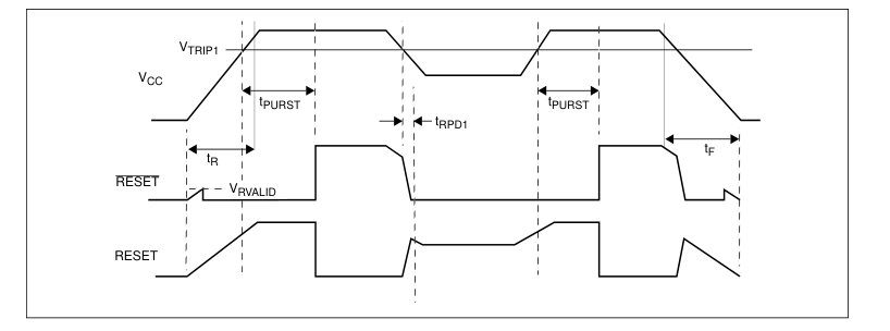
LOW VOLTAGE AND WATCHDOG TIMING PARAMETERS
| Symbol | Parameters | Min. | Typ.(1) | Max. | Unit |
|---|---|---|---|---|---|
| t (2) RPD1 | V to RESET/RESET (Power down only) TRIP1 | 5 | µs | ||
| t (2) RPDX | V to V2FAIL TRIP2 | 5 | µs | ||
| t PURST | Power On Reset delay: PUP1=0, PUP0=0 PUP1=0, PUP0=1 (factory setting) PUP1=1, PUP0=0 PUP1=1, PUP0=1 | 50 200(2) 400(2) 800(2) | ms ms ms ms | ||
| t F | V V2MON Fall Time CC, , | 20 | mV/µs | ||
| t R | V V2MON Rise Time CC, , | 20 | mV/µs | ||
| V RVALID | Reset Valid V CC | 1 | V | ||
| t WDO | Watchdog Timer Period: WD1=0, WD0=0 WD1=0, WD0=1 WD1=1, WD0=0 WD1=1, WD0=1 (factory setting) | 1.4(2) 200(2) 25 OFF | s ms ms | ||
| t RST1 | Watchdog Reset Time Out Delay WD1=0, WD0=0 WD1=0, WD0=1 | 100 | 200 | 300 | ms |
| t RST2 | Watchdog Reset Time Out Delay WD1=1, WD0=0 | 12.5 | 25 | 37.5 | ms |
| t RSP | Watchdog timer restart pulse width | 1 | µs |
Notes: (1) VCC = 5V at 25°C. (2) Values based on characterization data only.
Characteristics subject to change without notice. 19 of 25
Page 20
Watchdog Time Out For 2-Wire Interface
VTRIPX Set/Reset Conditions
Characteristics subject to change without notice. 20 of 25
Page 21
VTRIP1, VTRIP2, Programming Specifications: VCC = 2.0–5.5V; Temperature = 25°C
| Parameter | Description | Min. | Max. | Unit |
|---|---|---|---|---|
| t VPS | WDO Program Voltage Setup time | 10 | µs | |
| t VPH | WDO Program Voltage Hold time | 10 | µs | |
| t TSU | V Level Setup time TRIPX | 10 | µs | |
| t THD | V Level Hold (stable) time TRIPX | 10 | µs | |
| t WC | V Program Cycle TRIPX | 10 | ms | |
| t VPO | Program Voltage Off time before next cycle | 1 | ms | |
| V P | Programming Voltage | 15 | 18 | V |
| V TRAN1 | V Set Voltage Range TRIP1 | 2.0 | 4.75 | V |
| V TRAN2 | V Set Voltage Range – X40010/11 TRIP2 | 1.7 | 4.75 | V |
| V TRAN2A | V Set to Voltage Range – X40014/15 TRIP2 | 0.9 | 3.5 | V |
| V tv | V Set Voltage variation after programming (-40 to +85°C). TRIPX | -25 | +25 | mV |
| t VPS | WDO Program Voltage Setup time | 10 | µs |
Characteristics subject to change without notice. 21 of 25
Page 22
PACKAGING INFORMATION
8-Lead Plastic, SOIC, Package Code S8
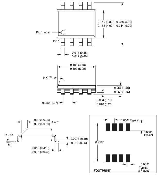
NOTE: ALL DIMENSIONS IN INCHES (IN PARENTHESES IN MILLIMETERS)
Characteristics subject to change without notice. 22 of 25
Page 23
PACKAGING INFORMATION
8-Lead Plastic, TSSOP, Package Code V8
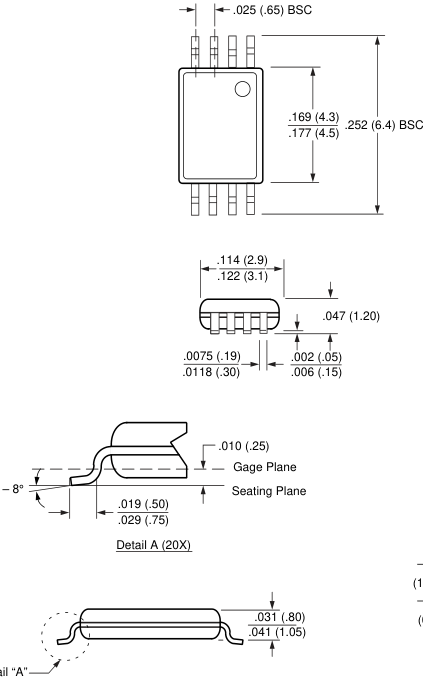
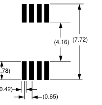
0° – 8°
All Measurements Are Typical
See Detail “A”
NOTE: ALL DIMENSIONS IN INCHES (IN PARENTHESES IN MILLIMETERS)
Characteristics subject to change without notice. 23 of 25
Page 24
ORDERING INFORMATION
| V CC Range | V TRIP1 Range | V Range TRIP2 | Package | Operating Temperature Range | Part Number with RESET | Part Number with RESET |
|---|---|---|---|---|---|---|
| 2.9-5.5 | 4.6V±50mV | 2.9V±50mV | 8L SOIC | 0oC - 70oC | X40010S8-A | X40011S8-A |
| -40oC - 85oC | X40010S8I-A | X40011S8I-A | ||||
| 8L TSSOP | 0oC - 70oC | X40010V8-A | X40011V8-A | |||
| -40oC - 85oC | X40010V8I-A | X40011V8I-A | ||||
| 2.6-5.5 | 4.4V±50mV | 2.6V±50mV | 8L SOIC | 0oC - 70oC | X40010S8-B | X40011S8-B |
| -40oC - 85oC | X40010S8I-B | X40011S8I-B | ||||
| 8L TSSOP | 0oC - 70oC | X40010V8-B | X40011V8-B | |||
| -40oC - 85oC | X40010V8I-B | X40011V8I-B | ||||
| 1.7-3.6 | 2.9V±50mV | 1.7V±50mV | 8L SOIC | 0oC - 70oC | X40010S8-C | X40011S8-C |
| -40oC - 85oC | X40010S8I-C | X40011S8I-C | ||||
| 8L TSSOP | 0oC - 70oC | X40010V8-C | X40011V8-C | |||
| -40oC - 85oC | X40010V8I-C | X40011V8I-C | ||||
| 1.3-3.6 | 2.9V±50mV | 1.3V±50mV | 8L SOIC | 0oC - 70oC | X40014S8-A | X40015S8-A |
| -40oC - 85oC | X40014S8I-A | X40015S8I-A | ||||
| 8L TSSOP | 0oC - 70oC | X40014V8-A | X40015V8-A | |||
| -40oC - 85oC | X40014V8I-A | X40015V8I-A | ||||
| 1.3-3.6 | 2.6V±50mV | 1.3V±50mV | 8L SOIC | 0oC - 70oC | X40014S8-B | X40015S8-B |
| -40oC - 85oC | X40014S8I-B | X40015S8I-B | ||||
| 8L TSSOP | 0oC - 70oC | X40014V8-B | X40015V8-B | |||
| -40oC - 85oC | X40014V8I-B | X40015V8I-B | ||||
| 1.0-3.6 | 2.9V±50mV | 1.0V±50mV | 8L SOIC | 0oC - 70oC | X40014S8-C | X40015S8-C |
| -40oC - 85oC | X40014S8I-C | X40015S8I-C | ||||
| 8L TSSOP | 0oC - 70oC | X40014V8-C | X40015V8-C | |||
| -40oC - 85oC | X40014V8I-C | X40015V8I-C |
PART MARK INFORMATION
8-Lead Package
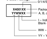
Package - S/V A, B, or C
I – Industrial Blank – Commercial
WW – Workweek YY – Year
Characteristics subject to change without notice. 24 of 25
Page 25
LIMITED WARRANTY
©Xicor, Inc. 2001 Patents Pending
Devices sold by Xicor, Inc. are covered by the warranty and patent indemnification provisions appearing in its Terms of Sale only. Xicor, Inc. makes no warranty, express, statutory, implied, or by description regarding the information set forth herein or regarding the freedom of the described devices from patent infringement. Xicor, Inc. makes no warranty of merchantability or fitness for any purpose. Xicor, Inc. reserves the right to discontinue production and change specifications and prices at any time and without notice. Xicor, Inc. assumes no responsibility for the use of any circuitry other than circuitry embodied in a Xicor, Inc. product. No other circuits, patents, or licenses are implied.
COPYRIGHTS AND TRADEMARKS
Xicor, Inc., the Xicor logo, E2POT, XDCP, XBGA, AUTOSTORE, Direct Write cell, Concurrent Read-Write, PASS, MPS, PushPOT, Block Lock, IdentiPROM, E2KEY, X24C16, SecureFlash, and SerialFlash are all trademarks or registered trademarks of Xicor, Inc. All other brand and product names mentioned herein are used for identification purposes only, and are trademarks or registered trademarks of their respective holders.
U.S. PATENTS
Xicor products are covered by one or more of the following U.S. Patents: 4,326,134; 4,393,481; 4,404,475; 4,450,402; 4,486,769; 4,488,060; 4,520,461; 4,533,846; 4,599,706; 4,617,652; 4,668,932; 4,752,912; 4,829,482; 4,874,967; 4,883,976; 4,980,859; 5,012,132; 5,003,197; 5,023,694; 5,084,667; 5,153,880; 5,153,691; 5,161,137; 5,219,774; 5,270,927; 5,324,676; 5,434,396; 5,544,103; 5,587,573; 5,835,409; 5,977,585. Foreign patents and additional patents pending.
LIFE RELATED POLICY
In situations where semiconductor component failure may endanger life, system designers using this product should design the system with appropriate error detection and correction, redundancy and back-up features to prevent such an occurrence. Xicor’s products are not authorized for use in critical components in life support devices or systems. 1. Life support devices or systems are devices or systems which, (a) are intended for surgical implant into the body, or (b) support or sustain life, and whose failure to perform, when properly used in accordance with instructions for use provided in the labeling, can be reasonably expected to result in a significant injury to the user.
- A critical component is any component of a life support device or system whose failure to perform can be reasonably expected to cause the failure of the life support device or system, or to affect its safety or effectiveness.
Characteristics subject to change without notice. 25 of 25