
X20121 UNITEDAUTOMATION
Document overview
- Manufacturer or author: Provided By www.digicamel.com(FREE DATASHEET DOWNLOAD SITE)
- PDF pages: 7
Technical content
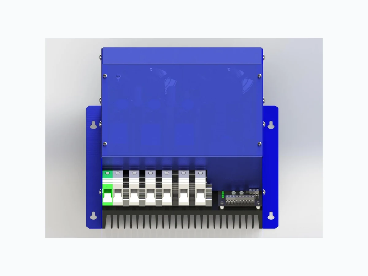
3-Phase Dual Mode Power Controller X20121
X20121 – DMPR3 86kW Instruction Manual Three Phase Dual Mode Power Controller Issue 4 UNITED AUTOMATION LTD Southport Business Park Tel: 0044 (0) 1704 – 516500 Wight Moss Way enquiries@united-automation.com Southport, PR8 4HQ www.united-automation.com ENGLAND unitedautomationltd UA_Limited Page 2 of 7 Issue: 4 Date: 21, September 2022
Contents
X20121 – DMPR3 86kW Instruction Manual Three Phase Dual Mode Power Controller Issue 4 UNITED AUTOMATION LTD Southport Business Park Tel: 0044 (0) 1704 – 516500 Wight Moss Way enquiries@united-automation.com Southport, PR8 4HQ www.united-automation.com ENGLAND unitedautomationltd UA_Limited Page 3 of 7 Issue: 4 Date: 21, September 2022
1 Introduction
The complete enclosed three phase Dual Mode Power Regulator (DMPR3) thyristor assembly provides control of inductive/resistive loads of up to 86 kW at 415V. The user selectable control modes, via the internal switches, are either phase - angle, burst-firing, or a combination of the two i.e., start up in phase angle and then continue in burst firing. The Single -Cycle & Dual -Cycle options offer the fastest burst rates possible, providing very accurate control and minimising Harmonic Distortion & Flicker within the system. In addition, the standard variable burst rate, adjustable from 1 to 30 seconds, is also available. There is a number of signal control options to meet most of the standard industrial requirements. All are housed in bespoke enclosures and have easy access to control signal & power terminals to aid installation. Semiconductor fuses and a heatsink with cooling fans. The controller offers a solution for many applications requiring single or dual mode control.
2 Applications
Suitable for:
- Furnaces
- Ovens
- Dryers
- Air curtains
- Hot plates
- Many other heating and ventilation applications
- Also suitable for inductive loads such as transformers
3 Function/Troubleshooting
Trip/Inhibit Input This input should be driven by a volt free contact. When the contact is closed, the power to the load will be disconnected, the relay changes state and the alarm LED will be illuminat ed for as long as the inhibit input is closed Over Temperature Protection When a heatsink tem perature of over 90 °C is detected by the sens or, the alarm relay changes state, and the alarm LED will flash alternatively every half second. The power to the load will be disconnected and will not be re-enabled until the heatsink temperature drops to approximately 85°C Phase Loss with Auxiliary Supply Only When any one of the three phase inputs are not present the relay changes state and will not be re-enabled until a current of voltage signal is detected, the ala rm LED will pul se ON/OFF every two seconds and the alarm relay state changes Offset Failure If there is no current signal (4-20mA), power to the load will be disconnected and will not be re- enabled until a current or voltage signal is detected, the Alarm LED will pulse ON/OFF every two seconds and the alarm relay state changes. Mode Mismatch If an incompatible mode has been selected, the Alarm LED will pulse ON/OFF every quarter second and the alarm relay state changes. Alarm Relay Fault Indication The alarm relay will be de-energised with no fault present and hence the NO contact will be open and dis-connected from the COM terminal, the relay state toggles when an alarm condition is detected. Remote Supply If there is a requirement for the alarm relay and Alarm LED to energise when a phase fault condition occurs an external 24V dc supply should be used.
X20121 – DMPR3 86kW Instruction Manual Three Phase Dual Mode Power Controller Issue 4 UNITED AUTOMATION LTD Southport Business Park Tel: 0044 (0) 1704 – 516500 Wight Moss Way enquiries@united-automation.com Southport, PR8 4HQ www.united-automation.com ENGLAND unitedautomationltd UA_Limited Page 4 of 7 Issue: 4 Date: 21, September 2022
4 Control Options Guide
Option SW1-1 – Brown When this switch is ON, the output is enabled to phase angle mode. The ramp speed is set by VR2 (0-30 Secs). The Status LED will proportionally increase in brightness as the control input signal is increased. Burst Firing Option SW1-2 – Red When this switch is ON, the output is enabled in burst fire mode. The Status LED will mimic the output pulses to the load as the control input signal is increased. Phase-Angle to Burst-Firing Control SW1-1 – Brown SW1-2 – Red The switch marked SW1 -1 and SW1-2 should be switched to the ON position. The firing circuit will start in phase angle mode and switch to burst mode when the control signal ramps up to the set point. It will stay in the burst mode even if the signal drops below the set point. It will restart in phase angle mode when the unit is switched off or reset. Rapid Burst Fire SW1-3 – Orange When switch SW1-3 is in the OFF position, standard burst fire is used. When in standard burst fire mode, the TIME BASE trimmer (VR1) is used to set the time base. The time base is the ON/OFF cycle time, this is variable from 1-30 seconds. When switch SW1-3 is in the ON position, rapid burst fire mode is selected. Two types of rapid burst fire are supported, single and dual cycle. Single cycle is selected when Burst Rate trimmer (VR1) is fully anticlockwise. Dual cycle is selected when Burst Rate trimmer (VR1) is fully clockwise. Offset Option SW1-4 – Yellow When SW1-4 is in the off position no offset is selected for the voltage and current input control signals. When SW1-4 is in the ON position an offset is introduced, this option is selected for 1-5V, 2- 10V and 4-20mA control signals. Voltage or Current Option SW1-5 – Green When switch SW1-5 is in the OFF position this selects a voltage control input signal (0-5V, 1-5V, 0- 10V, 2-10V). When switch SW1-5 is in the ON position this selects a current control signal (0-20mA, 4-20mA 3-wire or 4-wire SW1-6 – Blue When switch SW1-6 is in the ON position the controller is set for a 3-Wire configured load (Closed- Delta or Floating-Star), where there is no Neutral connection. When switch SW1-6 is in the OFF- position controller is set for 4-Wire configured load (Star to Neutral), where there is a Neutral connection to the Star Point. Inductive Load SW1-7 – Purple When switch SW1-7 in the OFF position, the firing circuit is configured to control resistive and some slightly inductive loads. When switch SW1-7 is in the ON position, the firing circuit should be used on inductive (transformer and coil) type loads. 0-5V/0-10V Signal Option SW1-8 – Grey When switch SW1-8 is in the OFF position the control voltage is selected to be 0-5V When switch SW1-8 is in the ON position the control voltage range is selected to be 0-10V or 1- 10V, depending on the Offset Option switch (SW1-4).
X20121 – DMPR3 86kW Instruction Manual Three Phase Dual Mode Power Controller Issue 4 UNITED AUTOMATION LTD Southport Business Park Tel: 0044 (0) 1704 – 516500 Wight Moss Way enquiries@united-automation.com Southport, PR8 4HQ www.united-automation.com ENGLAND unitedautomationltd UA_Limited Page 5 of 7 Issue: 4 Date: 21, September 2022
5 Installation
This robust stack assembly will operate in an ambient temperature of up to 40°C when naturally cooled and has a built -in 90°C, over temperature trip on the heatsink as a safety feature. The unit should be mounted vertically, with heatsink fins top to bottom and with sufficient surrounding air space to maximise natural convection cooling. If the unit is mounted in an enclosure or cabinet, adequate ve ntilation and/or forced air-cooling should be fitted.
5.1 Load Considerations
It is always advisa ble to indicate the type of load when ordering. For industrial reliability, based on long experience, the DMPR range has considerable current overload capacity on the power devices used. The rated currents are maximum continuous rms values for use within the temperature guidelines as shown in the table below. Unusual heating loads such as molybdenum, platinum or tungsten have a typical 10 to 1, hot to cold, resistance ratio and therefore, when cold, draw larger currents than normal. Transformers and other inductive loads have surge-starting currents and require the correct type of phase angle firing circuit. These and similar types of surge loads should be indicated, so that appropriate slow start or larger ra ted units can be correctly supplied for the specific needs.
5.2 Connections
This unit has simple clamp type connectors for all auxiliary-wiring requirements.
5.3 Power Supply
Three-way internal jumper J1 selects the internal power supply input voltage to either 420v or 460v ac rms, phase to phase. If the jumper link is fitted across HI-COM, 460v is selected with the jumper link fitted across COM -LO, 420v is selected. The jumper header is labelled as shown below: For operation with an external power supply the jumper link should be removed from J1.
5.4 Fusing
It is recommended that high speed semiconductor type fuses (as supplied) be used for protection. See SRA Data sheet X10255 f or further information. Other external supplies should be fused accordingly.
5.5 CE Marking
This family carries a “CE” markin g, in burst fire mode the controllers do not normally requires a remote filter. For more information contact our sales desk. A Declaration of Conformity is available on request.
X20121 – DMPR3 86kW Instruction Manual Three Phase Dual Mode Power Controller Issue 4 UNITED AUTOMATION LTD Southport Business Park Tel: 0044 (0) 1704 – 516500 Wight Moss Way enquiries@united-automation.com Southport, PR8 4HQ www.united-automation.com ENGLAND unitedautomationltd UA_Limited Page 6 of 7 Issue: 4 Date: 21, September 2022
6 Specifications
Power (Current) Rating 86kW (120A) Input Voltage 415V RMS +/- 10% Frequency 50/60Hz Control Signal Input Options 0-5VDC, 0-10VDC, 1-5VDC, 2-10VDC, 0-20mA, 4-20mA, Manual Potentiometer Using 5K Pot. Soft Start (Ramp Speed) 0-30 seconds (adjustable) Alarms Relay Contact Rating 2A @ 125VAC Max. Power Indicator Green Power LED Status indicator Status LED indicator changes intensity during phase angle and soft start or flashes in synchronisation with bursts Over Temperature Temperature trip activates @ 90°C, Alarm LED, and Status LED slow alternate flashes Temperature trip de-activates @ approximately 85°C Alarm Relay Default State Relay is de-energised in no fault state, NO contact is open (disconnected from COM) Phase Lose Detection Alarm LED and Status LED ‘flashes’ fast alternately Sensor Loss Detection Alarm LED indicator ‘flashes’ at quarter second intervals (approx. 4Hz) Fuse Failure Alarm LED indicator on solid Offset Failure Alarm LED indicator ‘flashes’ slow pulsing (approx. 0.5Hz) Mode Mismatch Alarm LED indicator ‘flashes’ fast pulsing (approx. 1Hz) Power Cable Size 86kW 35mm2 Cable Terminations Phase Power 35mm2 rising clamp terminal block Earth 35mm2 rising clamp terminal block Remote Supply, Alarm Relay, Inhibit, Control Signal 2.5mm2 rising clamp terminal block Terminal Torque Settings 3.2Nm minimum, 3.7Nm Maximum (35mm2) Power terminals only Fusing High-Speed semiconductor type fuses 86kW: 160EET (160A) Ambient Temperature 40°C without de-rating Dimensions (D x W x H)(mm) 277 x 300 x 130 Fixing Centres 4 x 5.5mm ø holes on centres 277mm (W) x 200mm (D) Weight 6.5kg
7 Safety Warnings
Isolate supply before removing cover; Metal parts, the heatsink, may get very hot when the unit is fully operational; DO NOT COVER enclosure ventilation slots. It is essential that a load break switch and contact breaker is installed in the supply. The supply to the contactor coil should be interrupted by an over-temperature thermostat located in the heater battery and by detection of airflow loss.
8 Recommendations
Additional supporting documents, which may be appropriate for your application, are available on request (see X10593).
9 Note
It is recommended that installation and maintenance of this equipment should be done with reference to the current edition of the I.E.T. (formally I.E.E.) regulations (BS7671) by suitably qualified/trained personnel. The regulations contain important requirements regarding installation and safety of electrical equipment. Specific installers should refer to local and national regulations. © These products are protected by unregistered design with United Automation Limited, Southport, UK
10 Order Details
When ordering directly, please use the following stock code: Manufacturer Stock Code Product Description Rating A481851 DMPR3 86kW 3-Phase, 86kW, 120A@415VAC, Full Control
X20121 – DMPR3 86kW Instruction Manual Three Phase Dual Mode Power Controller Issue 4 UNITED AUTOMATION LTD Southport Business Park Tel: 0044 (0) 1704 – 516500 Wight Moss Way enquiries@united-automation.com Southport, PR8 4HQ www.united-automation.com ENGLAND unitedautomationltd UA_Limited Page 7 of 7 Issue: 4 Date: 21, September 2022