
X20100 UNITEDAUTOMATION
Document overview
- Manufacturer or author: Provided By www.digicamel.com(FREE DATASHEET DOWNLOAD SITE)
- PDF pages: 7
Technical content
V YOU MUST READ THIS BEFORE INSTALLATION ELECTRICAL SAFETY INSTALLATION REQUIREMENTS USER RESTRICTIONS USAGE ENVIRONMENT HOT SURFACE WARNING WARNING: RISK OF ELECTRIC SHOCK Always consult the Installation & Maintenance Instructions before connecting this product to the power supply. WARNING: Disconnect Power Before Servicing Ensure the electrical supply is safely disconnected before connecting to any supply, load, or control terminals. WARNING: Installation by Qualified Personnel Only This product must only be installed or fitted by a competent, qualified installer familiar with the relevant electrical standards and installation practices. WARNING: Not for Use by Vulnerable Individuals This product is not intended for use by persons (including children) with reduced physical, sensory or mental capabilities, or lack of experience and knowledge, unless they are supervised or instructed by a person responsible for their safety. WARNING: Industrial Use Only This is an industrial-grade product and is not intended for household use. WARNING: Hot Surfaces On certain models, surfaces marked with this symbol become hot during use. Avoid direct contact and follow all thermal safety precautions. More Info: https://united-automation.com/general-product-safety-regulation-gpsr/
19 February 2026 | Issue: 9 Page 1 of 7
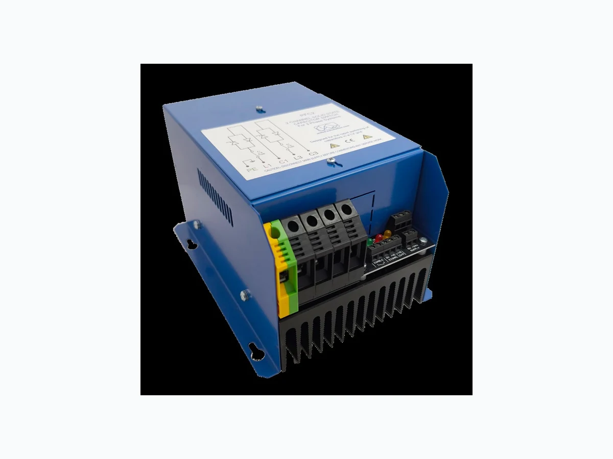
POWER FACTOR CORRECTION | THYRISTOR SWITCHING PFC2 Series X20100 30kVAR (50A), 50kVAR (75A), 415V Power Factor Switch – 2-Channel Controller 0044 (0) 1704-516 501 enquiries@united-automation.com www.united-automation.com CONTACT US: KEY FEATURES: The PFC2 Series Power Factor Switches provide precise and efficient switching for three-phase capacitive loads, enhancing power factor correction and reducing energy waste. Using the two-leg control technique, these controllers offer optimised capacitor switching with minimal inrush current. The PFC2 30kVAR & 50kVAR models feature integrated semiconductor fuses, an automatic resetting temperature trip, and fan cooling (on the 50kVAR model). The PFC2 Series delivers efficient power factor correction, reduced inrush current, and seamless switching for high-power applications. With advanced thermal protection, fault monitoring, and robust semiconductor fuses, these controllers ensure long-term reliability and energy efficiency. Optimise your power system today with the PFC2 Power Factor Switch! Enhanced Power Factor Correction: Optimises electrical efficiency and reduces reactive power. Low Inrush Current: Eliminates high start-up currents for capacitor banks. Rugged & Reliable: Features high-speed semiconductor fuses and enclosed panel mounting. Automatic Overtemperature Protection: Trips at 90°C and resets at 85°C. LED Status Indicators: Allows monitoring of power, faults, signal, and capacitor discharge. Alarm Relay Function: Provides a voltage-free relay for real-time fault detection. 50kVAR Fan Cooling: Automatically activates at 55°C to ensure longevity. TECHNICAL SPECIFICATIONS Power/(current ratings): 30kVAR (50A); 50kVAR (75A) @ a typical supply of 415V RMS Input voltage: 415V RMS +/- 10% Frequency: 50/60Hz External DC Supply: 24VDC (250mA) – Only when fuse failure monitoring is required Control signal input: 8 to 24V DC, Common 0V or Common +VE, Open Collector or Volt Free Contact Alarm relay functions: The voltage free alarm relay is rated for 125V ac @ 2A LED indicators: ■Green = DC Power ON, ■Red = Fault, ■Orange = Signal enabled, ■■Red/Orange = Capacitors discharging Cooling fan: 24V DC (NOTE: Fan fitted on 50KVAR model only) Fan ‘switch-on’: 50KVAR units typically 55 ºC Over Temperature: Trip in temperature @ 90ºC, +/- 1ºC (Status LED indicator ‘flashes’ with ON/OFF rapid pulsing Trip out temperature @ 85ºC, +/- 1ºC Phase loss detection: Phase loss or Fuse failure orange and red LEDs flash alternately Status LED Fault condition: Status LED indicator ‘flashes’ O N/OFF continuously at 1.5 second intervals Sensor loss detection: Status LED indicator ‘flashes’ ON/OFF continuously in equal intervals. Power cable terminations: Supply and Load16mm² rising clamp terminal block Earth16mm² rising clamp terminal block Terminal torque settings: 2.5Nm (16mm²) Power terminals only. Signal cable terminations: Remote supply Auxiliary alarm (relay) 2.5mm² rising clamp terminal block Control signal 2.5mm² rising clamp terminal block Protection: IP20 Fusing 30kVAR: 50kVAR: 80ET (80A) High-Speed Semiconductor type fuse, or equivalent 100ET (100A) High-Speed Semiconductor type fuse, or equivalent Control circuit protection F1A Control Circuit Protection fuse (On PCB next to Transformer) Working temperature: 65°C (maximum operational) Dimensions: 205mm (D) x 155mm (W) x 120mm (H) 30KVAR 250mm (D) x 155mm (W) x 120mm (H) 50KVAR Fixing centres: 4 x 4.5mm-clear keyhole slots on fixing centres 140mm (W) x 140mm (D) Weight: (30kVAR) 3.0kg (50kVAR) 3.4kg Note: SAFETY WARNING – Isolate supply before removing cover; Metal parts, in particular the case may get very hot when the unit is fully operational; DO NOT COVER enclosure ventilation slots. APPLICATIONS: Ideal for power factor correction (PFC) in capacitor banks, these solid-state controllers are widely used in Industrial power systems, Welding plants, lifts and cranes, Wind turbines, and High-Power capacitive loads.
X20100 POWER FACTOR CORRECTION | THYRISTOR SWITCHING PFC2 Series 30kVAR (50A), 50kVAR (75A), 415V Power Factor Switch – 2-Channel Controller BMF House - Wight Moss Way, Southport Business Park Southport PR8 4HQ ENGLAND, UNITED KINGDOM Contact Us: 0044 (0) 1704-516 501 enquiries@united-automation.com www.united-automation.com unitedautomationltd UA_Limited 19 February 2026 | Issue: 9 Page 2 of 7 INSTALLATION If the PFC2 controllers are mounted in a control panel, they should be mounted in a vertical position with the heat sink fins running top to bottom. Care must be taken to ensure that sufficient cooling is available for the PFC2 power switches; in continuous operation at maximum current, the heat sink temperature can reach 90ºC. Ensure that the heat sink fins are not obstructed by cables or ducting and that the controllers are not fixed directly above one another. Ensure the cabinet is cooled sufficiently to avoid the controllers tripping on over temperature; they will reset when the temperature drops below 85ºC, but they will be out of action for that period of time. Maximum dissipated heat:
- 1 x PFC2 controller 30KVAR at 400V AC, 2 x 44A is approximately 80W.
- 1 x PFC2 controller 100KVAR at 400V AC, 2 x 72A is approximately 130W. Load Considerations The PFC2 series of power controllers are designed for 3-wire, 3-phase floating-star or closed delta configured capacitive loads. For further information on configured loads, see our supporting datasheet - AC Power Control Specifications and Application Circuits (APC - ref. X10322). Cooling requirements This robust stack assembly has an operational temperature of 65°C when naturally cooled and has a built -in 90°C over temperature trip on the heatsink as a safety feature. The unit should be mounted vertically, with heatsink fins aligned top to bottom and with sufficient surrounding air space to maximise natural convection cooling. If the unit is mounted in an enclosure or cabinet, adequate ventilation and/or forced air cooling should be fitted. The 50kVAR controller has a fan which is normally off but automatically turns on at high heatsink temperature (see SPECIFICATIONS – Fan switch-on and over temperature.) CONNECTIONS This unit has clamp-type connectors for all auxiliary wiring requirements. Please see Fig. 1, Fig. 2, and Fig. 3 below. NOTE: The controller is factory set for an internal power supply. For alternative ‘voltage free’ alarm supply details, see the Functions section. Please contact our Technical support for further details.
X20100 POWER FACTOR CORRECTION | THYRISTOR SWITCHING PFC2 Series 30kVAR (50A), 50kVAR (75A), 415V Power Factor Switch – 2-Channel Controller BMF House - Wight Moss Way, Southport Business Park Southport PR8 4HQ ENGLAND, UNITED KINGDOM Contact Us: 0044 (0) 1704-516 501 enquiries@united-automation.com www.united-automation.com unitedautomationltd UA_Limited 19 February 2026 | Issue: 9 Page 3 of 7
X20100 POWER FACTOR CORRECTION | THYRISTOR SWITCHING PFC2 Series 30kVAR (50A), 50kVAR (75A), 415V Power Factor Switch – 2-Channel Controller BMF House - Wight Moss Way, Southport Business Park Southport PR8 4HQ ENGLAND, UNITED KINGDOM Contact Us: 0044 (0) 1704-516 501 enquiries@united-automation.com www.united-automation.com unitedautomationltd UA_Limited 19 February 2026 | Issue: 9 Page 4 of 7
X20100 POWER FACTOR CORRECTION | THYRISTOR SWITCHING PFC2 Series 30kVAR (50A), 50kVAR (75A), 415V Power Factor Switch – 2-Channel Controller BMF House - Wight Moss Way, Southport Business Park Southport PR8 4HQ ENGLAND, UNITED KINGDOM Contact Us: 0044 (0) 1704-516 501 enquiries@united-automation.com www.united-automation.com unitedautomationltd UA_Limited 19 February 2026 | Issue: 9 Page 5 of 7 Control Options – Fig. 3
X20100 POWER FACTOR CORRECTION | THYRISTOR SWITCHING PFC2 Series 30kVAR (50A), 50kVAR (75A), 415V Power Factor Switch – 2-Channel Controller BMF House - Wight Moss Way, Southport Business Park Southport PR8 4HQ ENGLAND, UNITED KINGDOM Contact Us: 0044 (0) 1704-516 501 enquiries@united-automation.com www.united-automation.com unitedautomationltd UA_Limited 19 February 2026 | Issue: 9 Page 6 of 7 FUNCTIONS Operation These solid state capacitor switches are comprised of two anti-parallel thyristor diode modules, with appropriate transient protection connected across them. These modules are mounted on a heat sink and are controlled by a microprocessor-based trigger module, which determines the precise time to trigger the thyristor so as to eliminate any high current switching transients. The processor monitors the heat sink temperature of both the 30 and 50 kVAR models. On the 50 kVAR model, the cooling fan will switch on when the heat sink temperature reaches 55ºC. Both models will turn off if the heat sink temperature rises above 90ºC, and will reset again when the temperature drops below 85ºC. Switching of the controller is via a control signal from 8 to 24V DC, which can be supplied from an external power supply (J2 EXT). These input signals can be either common positive or common negative. You can also use the onboard internal DC power supply (J2 INT), which provides a +12V DC output. This can be fed back into the controller into the +VE SIGNAL input via ‘volt-free’ contacts or semiconductor switches. The maximum DC voltage present when the thyristors are not conducting can be 150% of the peak mains voltage, so any discharge resistors used should be rated accordingly. Discharge reactors should not be used because the continuous DC voltage that is present would destroy them. It is recommended that discharge resistors are used and that they are designed to meet the peak DC voltages which may be seen in a permanent installation. Fault delay timer VR1 This allows the power factor load capacitors to discharge before indicating a possible fault condition. The following table shows some recommended settings for various kVAR ratings. POWER IN KVAR DELAY TIME IN SECONDS VR1 SETTING 25 20 1 50 40 2 Fan Activation – 50 kVAR Unit When the temperature of the heat sink reaches 55ºC, the cooling fan is activated and will remain on until the heat sink temperature drops below 50ºC. Over Temperature Alarm If the temperature of the heat sink reaches 90ºC, the red fault LED will flash rapidly, the controller and the orange status LED will turn off, and the fault relay will energise. When the heat sink temperature drops below 85ºC, the controller will reset, the status LED will come back on, the red fault LED will turn off, and the relay will de- energise. Fuse Fail Alarm – (External DC Supply Needed) If the supply or fuse fails in either the L1 or L3 inputs, the red fault LED and the orange status LED will flash alternately. If the control signal is turned on during this period, the red fault LED and the relay will energise and remain latched on continuously until the firing card power supply is turned off. The controller must be powered down in order to reset. Enable Input The contacts of the enable input must be closed for the controller to operate.
X20100 POWER FACTOR CORRECTION | THYRISTOR SWITCHING PFC2 Series 30kVAR (50A), 50kVAR (75A), 415V Power Factor Switch – 2-Channel Controller BMF House - Wight Moss Way, Southport Business Park Southport PR8 4HQ ENGLAND, UNITED KINGDOM Contact Us: 0044 (0) 1704-516 501 enquiries@united-automation.com www.united-automation.com unitedautomationltd UA_Limited 19 February 2026 | Issue: 9 Page 7 of 7 Maintenance Generally, thyristor switches are maintenance-free; however, the following checks are recommended to ensure reliable operation:
- The 50kVAR controller is fitted with a cooling fan, which should be inspected every two years. If the fan is found to be defective, it must be replaced with one of the same type and specification.
- Heat sinks should be inspected regularly to ensure the fins are free from dust, debris, or any obstruction that could impair cooling. The thyristor terminals should also be checked to confirm they remain clean and free from contamination.
- Continuous over-temperature tripping will be indicated by the normally open contacts of the alarm relay closing. This may suggest that one of the above fault conditions has occurred. Note: All electrical terminations should be inspected in accordance with the scheduled maintenance programme. RECOMMENDATIONS FUSING It is recommended that fast acting semiconductor type fuses (as supplied) be used for protection. See SRA Data sheet X10255 for further information. It is recommended that supply fuses are installed in the load supply. CE Marking This family carries a “CE” marking. These burst fire controllers do not normally require a remote filter. For more information contact our sales desk. A Declaration of Conformity is available on request. DOCUMENTS Other documents available on request, which may be appropriate for your application: Code Identity Description X10213 ITA Interaction: Uses for phase angle and for burst fire control X10255 SRA Safety Requirements: Addressing the Low Voltage Directive (LVD) including, Thermal Data/Cooling, Live Parts Warning, Earthing Requirements and Fusing Recommendations P01.1 COS UAL Conditions of Sale It is recommended that installation and maintenance of this equipment should be done with reference to the current edition of the I.E.T. regulations (BS7671) by suitably qualified/trained personnel. The regulations contain important requirements regarding the safety of electrical equipment. For International standards refer STANDARDS on D of C. OPTIONAL EXTRAS Product Code Product Description Available on request Spare HS fuses: 80ET (80A) or 100ET (100A) SCR-type PRODUCT CODE AND RELATED PRODUCT CODE Product Code Product Description A418301 PFC2 30kVAR, 50A, 415V, 2/3rds control - Three Phase A418302 PFC2 50kVAR, 75A, 415V, 2/3rds control - Three Phase © These products are protected by unregistered design with United Automation Limited, Southport, UK