
X20012 UNITEDAUTOMATION
Document overview
- Manufacturer or author: Provided By www.digicamel.com(FREE DATASHEET DOWNLOAD SITE)
- PDF pages: 5
Technical content
YOU MUST READ THIS BEFORE INSTALLATION ELECTRICAL SAFETY INSTALLATION REQUIREMENTS USER RESTRICTIONS USAGE ENVIRONMENT HOT SURFACE WARNING WARNING: RISK OF ELECTRIC SHOCK Always consult the Installation & Maintenance Instructions before connecting this product to the power supply. WARNING: Disconnect Power Before Servicing Ensure the electrical supply is safely disconnected before connecting to any supply, load, or control terminals. WARNING: Installation by Qualified Personnel Only This product must only be installed or fitted by a competent, qualified installer familiar with the relevant electrical standards and installation practices. WARNING: Not for Use by Vulnerable Individuals This product is not intended for use by persons (including children) with reduced physical, sensory or mental capabilities, or lack of experience and knowledge, unless they are supervised or instructed by a person responsible for their safety. WARNING: Industrial Use Only This is an industrial-grade product and is not intended for household use. WARNING: Hot Surfaces On certain models, surfaces marked with this symbol become hot during use. Avoid direct contact and follow all thermal safety precautions. More Info: https://united-automation.com/general-product-safety-regulation-gpsr/
1 July 2025 | Issue: 7 Page 1 of 5
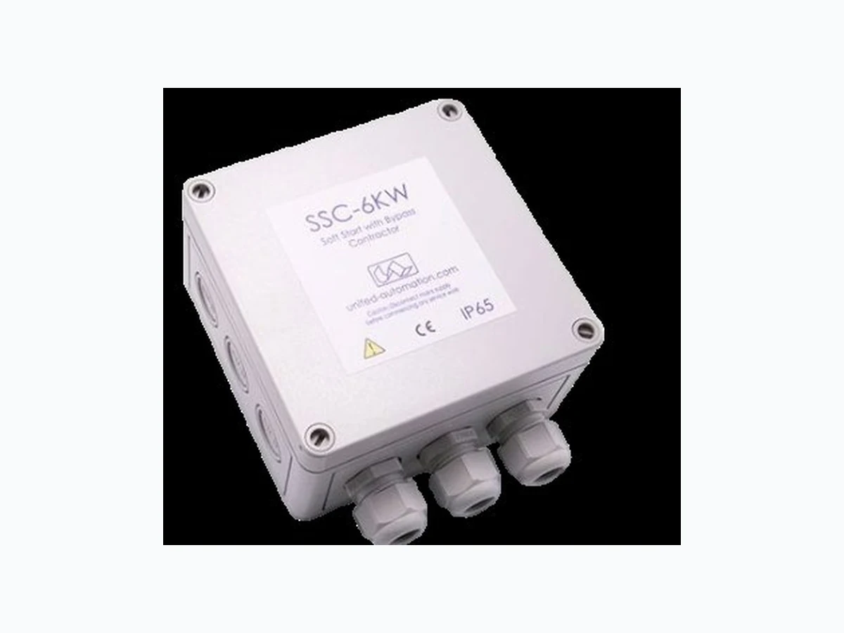
110V, 230V – 3kW, 6kW Enhance Load Protection and Efficiency 0044 (0) 1704-516 501 enquiries@united-automation.com www.united-automation.com CONTACT US: KEY FEATURES: The Soft Start Controller with Contactor is designed to seamlessly manage the power-up process for both inductive and resistive loads, ensuring a smooth and controlled ramp-up that eliminates high inrush current. With a ramp-on time adjustable between 1 to 5 seconds and a pedestal value range of 0-40%, this device offers precise control to protect your equipment and prevent nuisance MCB trips. Enhance the longevity and reliability of your electrical equipment with the Soft Start Controller with Contactor, designed for optimal performance and protection in demanding applications. Smooth Ramp-Up: Adjustable 1-5 second ramp-on time to prevent sudden surges. Pedestal Control: Allows for 0-40% adjustment of the sine wave start. High Switching Capacity: Handles up to 6kW at 230V AC and 3kW at 110V AC. Durable Construction: IP65 rated enclosure to withstand harsh environments. Easy Installation: Equipped with 6.0mm² rising clamp terminals and a max cable entry diameter of 2.5mm². TECHNICAL SPECIFICATIONS Supply Voltage 230V AC ±10% @ 50/60Hz Switching Capacity 6kW Max AT 230v AC 3Kw at 110v AC Ramp On-Time 1-5 Seconds Pedestal Value 0-40% (Conduction Angle) Current Consumption 20mA Terminals 6.0mm2 Rising Clamp Operating Temperature -20 to 40°C Protection Rating IP65 Gland Diameter Max. Cable Entry 2.5mm2 Enclosure Dimensions (W x L x H) 130 x 130 x 75mm Supply Voltage 230V AC ±10% @ 50/60Hz Switching Capacity 6kW Max AT 230v AC 3Kw at 110v AC APPLICATIONS: The Soft Start Controller with Contactor is perfect for: Transformers: Ensures smooth startups, preventing inrush current damage. Motors: Provides controlled power-up, extending motor lifespan. Compressors: Protects against electrical surges during startup. Resistive Loads: Guarantees safe and efficient operation for various resistive loads.
Soft Start Controller with Bypass Contactor 110V, 230V – 3kW, 6kW Enhance Load Protection and Efficiency BMF House - Wight Moss Way, Southport Business Park Southport PR8 4HQ ENGLAND, UNITED KINGDOM Contact Us: 0044 (0) 1704-516 501 enquiries@united-automation.com www.united-automation.com unitedautomationltd UA_Limited 1 July 2025 | Issue: 7 Page 2 of 5 INSTALLATION SAFETY FIRST! Please read these instructions thoroughly before installing and operating this product. Positioning and Mounting:
- Position the Soft Start unit with the three fixed cable glands facing downward.
- Secure the unit using the four mounting holes accessible from the front.
- Use round cables to avoid water ingress.
- A mounting template is provided to locate the four mounting hole centres. Wiring Important: Installation and maintenance should be performed by qualified personnel, referencing the current edition of the I.E.E. wiring regulations (BS7671) for safety compliance (International Standards refer to I.E.C/directive IEC950). Warning: Isolate the mains supply before beginning any work on the unit to avoid serious injury or fatality.
- Cable Glands: The unit has three cable glands: o Left gland: For the mains supply o Middle gland: For the load o Right gland: For the enable input Note: Only one cable per gland should be used to maintain the unit's IP rating. Connections:
- Mains Supply: Connect to the terminal block marked 'LINE'. o Live (L) to 'L' terminal o Neutral (N) to 'N' terminal o Earth (E) to 'E' terminal
- Load: Connect to the terminal block marked 'LOAD'. o Live (L) to 'L' terminal o Neutral (N) to 'N' terminal o Earth (E) to 'E' terminal
- Enable Input: o If an external enable signal is used, connect to the terminal block marked 'ENABLE'. o If no enable input is needed, insert a wire link into the Enable terminal. Important: Ensure all earth wires are connected to maintain earth continuity. Double-check all wiring and ensure the cable glands are tightly secured.
Soft Start Controller with Bypass Contactor 110V, 230V – 3kW, 6kW Enhance Load Protection and Efficiency BMF House - Wight Moss Way, Southport Business Park Southport PR8 4HQ ENGLAND, UNITED KINGDOM Contact Us: 0044 (0) 1704-516 501 enquiries@united-automation.com www.united-automation.com unitedautomationltd UA_Limited 1 July 2025 | Issue: 7 Page 3 of 5 Commissioning 1. Set the Secs Cermet (VR2) to a value between 1 and 5 seconds. 2. If the Pedestal (VR1) is used, adjust it to a position between 0-40%. If not used, set it to 0%. 3. If an enable switch is needed, remove the link from the ENABLE terminal and attach the switch. 4. Replace the lid and switch on the mains supply to the unit. 5. The soft start should activate upon power-on if the link is fitted or when the ENABLE switch is engaged. By following these instructions, you ensure the safe and efficient installation and operation of your Soft Start unit. Troubleshooting Warning: Isolate the mains supply before commencing any work on the unit. Failure to do so could result in serious injury or fatality. Problem Solution System Doesn’t Start 1. Verify Mains Supply: Ensure that the mains supply to the unit is switched on. 2. Check Enable Link: Confirm that the Enable Link is properly fitted. 3. Inspect Wiring Connections: o Check the LINE and LOAD wiring connections to both the unit and the load. 4. Contact Supplier: If the problem persists, contact your supplier for further assistance. 5. Recommendations & Safety Requirements WIRING DIAGRAM
Soft Start Controller with Bypass Contactor 110V, 230V – 3kW, 6kW Enhance Load Protection and Efficiency BMF House - Wight Moss Way, Southport Business Park Southport PR8 4HQ ENGLAND, UNITED KINGDOM Contact Us: 0044 (0) 1704-516 501 enquiries@united-automation.com www.united-automation.com unitedautomationltd UA_Limited 1 July 2025 | Issue: 7 Page 4 of 5 Mounting Template IMPORTANT! The unit must be orientated when wall mounting with the cable glands facing down.
Soft Start Controller with Bypass Contactor 110V, 230V – 3kW, 6kW Enhance Load Protection and Efficiency BMF House - Wight Moss Way, Southport Business Park Southport PR8 4HQ ENGLAND, UNITED KINGDOM Contact Us: 0044 (0) 1704-516 501 enquiries@united-automation.com www.united-automation.com unitedautomationltd UA_Limited 1 July 2025 | Issue: 7 Page 5 of 5 RECOMMENDATIONS FUSING It is recommended to use semiconductor (fast acting) type fuses or circuit breakers (Semiconductor - MCB) for unit protection. On initial switch on some loads may need an increased Factor of Safety (F of S) for unit and/or device protection. See SRA datasheet for information. DOCUMENTS Other documents available on request, which may be appropriate for your application: Code Identity Description X10255 SRA Safety Requirements: Addressing the Low Voltage Directive (LVD) including, Thermal Data/Cooling, Live Parts Warning, Earthing Requirements and Fusing Recommendations P01.1 COS UAL Conditions of Sale It is recommended that installation and maintenance of this equipment should be done with reference to the current edition of the I.E.T. regulations (BS7671) by suitably qualified/trained personnel. The regulations contain important requirements regarding the safety of electrical equipment. For International standards refer STANDARDS on D of C. PRODUCT CODE AND RELATED PRODUCT CODE Product Code Product Description A403156 SSC-6kW - 230VAC - Soft Start Controller with Bypass Contactor A403158 SSC-3kW - 110VAC - Soft Start Controller with Bypass Contactor