
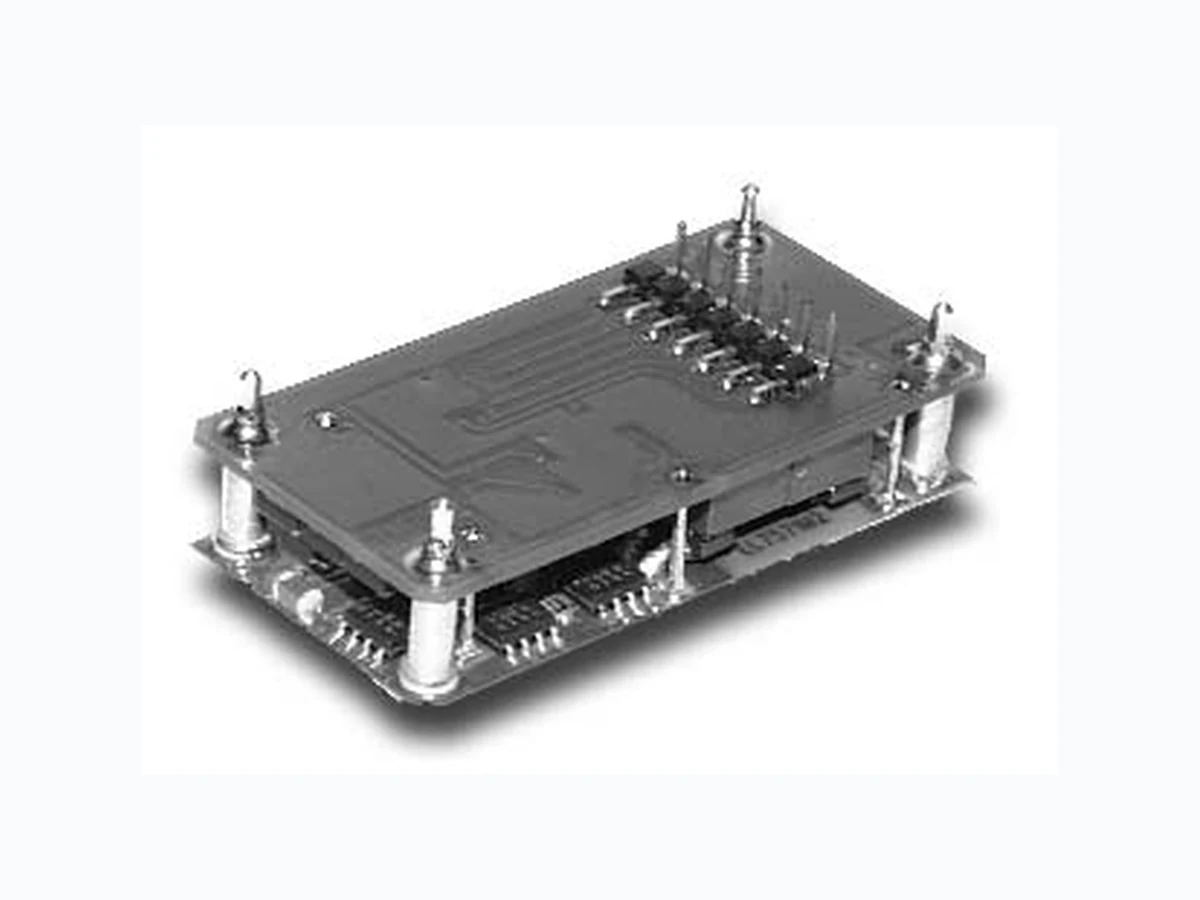
UPM-EA POWER-ONE
Document overview
- Manufacturer or author: Provided By www.digicamel.com(FREE DATASHEET DOWNLOAD SITE)
- PDF pages: 4
Technical content
Features
The UPM-EA programmable DC-DC converter is a high efficiency, step-down converter. The UPM-EA incorporates a 5-bit DAC output voltage control which is compliant with standard VRM VID Protocol. The UPM-EA provides up to 45 watts of output power at 13A output current, and at output voltages from 1.30 to 3.50V . Featuring open-frame, 100% surface-mount construction and high efficiency topology, the UPM-EA excels in difficult thermal environments. Technical Specifications
- 5-bit programmable output
- High efficiency topology
- Excellent transient response
- Power Good signal
- Surface-mount construction
- Short-circuit protection
- Low profile
- Water washable Switching Frequency 200 kHz Temperature Coefficient 50ppm/°C Baseplate Operating Temperature 0 to +100°C Storage Range -40 to +100°C Internal Input Capacitance 500 µF Max. Recommended External Capacitance Input 100 µF/A Iout Output 100 µF/A Iout MTBF† (Bellcore TR-NWT-000332) 2.9 x 10 6 hrs Safety UL, CSA Weight (approx.) 0.9 oz General Output Voltage Range 5 VDC Nominal 4.5 - 5.5 VDC Input Undervoltage Lockout, Power On 3.6 - 4.4 VDC Input Undervoltage Lockout, Power Down 3.15 - 3.85 VDC Startup Time 10 ms Input Setpoint Accuracy See Output Voltage Table Line Regulation Vin Min. - Vin Max., Iout Rated See Output Voltage Table Load Regulation Iout Min. - Iout Max., Vin Nom. See Output Voltage Table Ripple and Noise, DC - 20 MHz †† 50 mV Pk-Pk Current Limit Protection Type Hiccup Current Limit Threshold Range, % of I out Rated 130% Short Circuit Protection Type Hiccup Power Good Signal Characteristics Asserts Logic “High” When Vout is Between Following Levels Lower Threshold, % Vout Programmed -16% to -10% Upper Threshold, % Vout Programmed +10% to +16% 10 20 30 40 50 60 70 80 90 100 LOAD % EFFICIENCY % EFF. (4.5v) EFF. (5v) EFF. (5.5v) Efficiency vs. Load Notes † MTBF predictions may vary slightly from model to model. †† When used with recommended capacitors Specifications typically at 25°C, normal line, and full load, unless otherwise stated. Soldering Conditions: I/O pins, 260°C, ten seconds; fully compatible with commercial wave-soldering equipment. Safety: Agency approvals may vary from model to model. Please consult factory for specific model information. Units are water-washable and fully compatible with commercial spray or immersion post wave-solder washing equipment. THE UPM-EA SERIES IS NOT FOR NEW DESIGNS.
P4 P3 P2 P1 P0 OUTPUT TOTAL ERROR VOLTAGE BAND 1 1 1 1 1 0.00 ±24 mV 0 1 1 1 1 1.30 ±24 mV 0 1 1 1 0 1.35 ±24 mV 0 1 1 0 1 1.40 ±24 mV 0 1 1 0 0 1.45 ±24 mV 0 1 0 1 1 1.50 ±24 mV 0 1 0 1 0 1.55 ±24 mV 0 1 0 0 1 1.60 ±24 mV 0 1 0 0 0 1.65 ±24 mV 0 0 1 1 1 1.70 ±24 mV 0 0 1 1 0 1.75 ±24 mV 0 0 1 0 1 1.80 ±24 mV 0 0 1 0 0 1.85 ±24 mV 0 0 0 1 1 1.90 ±24 mV 0 0 0 1 0 1.95 ±24 mV 0 0 0 0 1 2.00 ±24 mV 0 0 0 0 0 2.05 ±24 mV 1 1 1 1 0 2.10 ±24 mV 1 1 1 0 1 2.20 ±24 mV 1 1 1 0 0 2.30 ±24 mV 1 1 0 1 1 2.40 ±24 mV 1 1 0 1 0 2.50 ±25 mV 1 1 0 0 1 2.60 ±26 mV 1 1 0 0 0 2.70 ±27 mV 1 0 1 1 1 2.80 ±28 mV 1 0 1 1 0 2.90 ±29 mV 1 0 1 0 1 3.00 ±30 mV 1 0 1 0 0 3.10 ±31 mV 1 0 0 1 1 3.20 ±32 mV 1 0 0 1 0 3.30 ±33 mV 1 0 0 0 1 3.40 ±34 mV 1 0 0 0 0 3.50 ±40 mV NOTE: Logic “0” < 1.5V; Logic “1” > (Vin - 1.5V). Total Error Band includes initial setpoint accuracy, line, and load regulation. REV. JUN 02, 2004 Programmable-Output, 45 Watts Page 2 of 4 UPM-EA DC-DC Series Data Sheet THE UPM-EA SERIES IS NOT FOR NEW DESIGNS.
UPM-EA DC-DC Series Data Sheet Programmable-Output, 45 Watts Page 3 of 4 REV. JUN 02, 2004 Mechanical Drawing /K31/K30 /K39 /K38 /K37 /K36 /K35 /K34 /K33 /K32 /K31 /K42/K4F/K54/K54/K4F/K4D /K56/K49/K45/K57 /K2D/K30/K2E/K31/K32/K35/K22/K28/K2D/K33/K2E/K32/K6D/K6D/K29 /K30/K2E/K36/K32/K35/K22/K28/K31/K35/K2E/K39/K6D/K6D/K29 /K30/K2E/K35/K32/K35/K22/K28/K31/K33/K2E/K33/K6D/K6D/K29 /K30/K2E/K34/K32/K35/K22/K28/K31/K30/K2E/K38/K6D/K6D/K29 /K30/K2E/K33/K32/K35/K22/K28/K38/K2E/K33/K6D/K6D/K29 /K30/K2E/K32/K32/K35/K22/K28/K35/K2E/K37/K6D/K6D/K29 /K30/K2E/K31/K32/K35/K22/K28/K33/K2E/K32/K6D/K6D/K29 /K30/K2E/K37/K35/K30/K22/K28/K31/K39/K2E/K30/K6D/K6D/K29 /K30 /K28/K31/K32/K2E/K31/K6D/K6D/K29 /K30/K2E/K34/K37/K35/K22 /K28/K33/K2E/K30/K6D/K6D/K29 /K30/K2E/K31/K32/K22 /K28/K31/K2E/K35/K6D/K6D/K29 /K44/K49/K41 /K30/K2E/K30/K36/K30/K22 /K28/K30/K2E/K36/K6D/K6D/K29 /K30/K2E/K30/K32/K35/K22 /K53/K51/K2E /K28/K35/K30/K2E/K38/K6D/K6D/K29 /K32/K2E/K30/K30/K22 /K31/K2E/K30/K30/K22 /K28/K32/K35/K2E/K34/K6D/K6D/K29 /K30 /K28/K2D/K33/K2E/K32/K6D/K6D/K29 /K2D/K30/K2E/K31/K32/K35/K22 /K28/K33/K37/K2E/K35/K6D/K6D/K29 /K31/K2E/K34/K37/K35/K22 /K28/K34/K34/K2E/K35/K6D/K6D/K29 /K31/K2E/K37/K35/K30/K22 Natural Convection 9.4 °C/W 100 LFM 6.6 °C/W 200 LFM 4.3 °C/W 300 LFM 3.2 °C/W 400 LFM 2.7 °C/W Thermal Impedance Note: Thermal impedance data is dependent on many environmental factors. The exact thermal performance should be validated for specific application. Tolerances Inches: (Millimeters) Pin: ± 0.002 ± 0.05 (Dimensions as listed unless otherwise specified.) Pin Function 1- V in 2+ V in 3- V out 4+ V out 5P 4 6P 3 7P 2 8P 1 9P 0
10 Ground
11 Power Ground
FOR NEW DESIGNS.
REV. JUN 02, 2004 This page is offered as a reference. Consult factory for actual availability of options. When ordering equipment options, use the following suffix information. Select preferred option(s) and add the suffix to the model number. Ordering option examples are located below the options table. NUCLEAR AND MEDICAL APPLICATIONS - Power-One products are not authorized for use as critical components in life support systems, equipment used in hazardous environments, or nuclear control systems without the express written consent of the respective divi sional president of Power-One, Inc. TECHNICAL REVISIONS - The appearance of products, including safety agency certifications pictured on labels, may change dependin g on the date manufactured. Specifications are subject to change without notice. OPTION SUFFIX APPLICABLE SERIES REMARKS Negative Logic N HAS, HBD, HBS, HES, HLS, HLD, LES, TTL "Low" Turns Module ON QBS, QES, QLS, TES, TQD TTL "High" Turns Module OFF Lucent-Compatible Trim T HAS, HBD, HBS, HES, HLS, QBS, QES, QLS Trim 1 IAS, LES Enable 2 IAD, IAS, LES, SMS Trim and Enable 3 IAS, LES Pin Length and Heat Sink Options Standard Pin Length is 0.180" (4.6mm) 0.110" (2.8mm) Pin Length 8 All Leaded Models 0.150" (3.8mm) Pin Length 9 All Leaded Models 0.24" (6.1mm) Horizontal Heat Sink 1H All 1/4-Bricks, 1/2-Bricks, 3/4-Bricks, Full-Bricks Includes Thermal Pad (Except HLS, HLD, QLS, TLD, and TKD Packages) 0.24" (6.1mm) Vertical Heat Sink 1V All 1/4-Bricks, 1/2-Bricks, 3/4-Bricks, Full-Bricks Includes Thermal Pad (Except HLS, HLD, QLS, TLD, and TKD Packages) 0.45" (11.4mm) Horizontal Heat Sink 2H All 1/4-Bricks, 1/2-Bricks, 3/4-Bricks, Full-Bricks Includes Thermal Pad (Except HLS, HLD, QLS, TLD, and TKD Packages) 0.45" (11.4mm) Vertical Heat Sink 2V All 1/4-Bricks, 1/2-Bricks, 3/4-Bricks, Full-Bricks Includes Thermal Pad (Except HLS, HLD, QLS, TLD, and TKD Packages) 0.95" (24.1mm) Horizontal Heat Sink 3H All 1/4-Bricks, 1/2-Bricks, 3/4-Bricks, Full-Bricks Includes Thermal Pad (Except HLS, HLD, QLS, TLD, and TKD Packages) 0.95" (24.1mm) Vertical Heat Sink 3V All 1/4-Bricks, 1/2-Bricks, 3/4-Bricks, Full-Bricks Includes Thermal Pad (Except HLS, HLD, QLS, TLD, and TKD Packages) Example Options: HBS050ZG-ANT3V = HBS050ZG-A with negative logic, Lucent-compatible trim, and 0.95” vertical heat sink. LES015YJ-3N = LES015YJ with optional trim and enable, negative logic. QBS066ZG-AT8 = QBS066ZG-A with Lucent-compatible trim and 0.110” pin length.