


 Download PDF
UMT0G101MDD NICHICON
Document overview
- PDF pages: 1
Technical content
Page 1
ALUMINUM ELECTROLYTIC CAPACITORS
MT series
5mmL, Wide Temperature Range
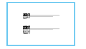
Wide temperature range of –55 ~ +105°C, with 5mm height.
Adapted to the RoHS directive (2002/95/EC).
MT
MV Long life
High Temperature MA
Specifications
| Item | Performance Characteristics |
| Category Temperature Range | –55 ~ +105°C |
| Voltage Range | 4 ~ 50V |
| Rated Capacitance Range | 0.1 ~ 100µF |
| Rated Capacitance Tolerance | ±20% at 120Hz, 20°C |
| Leakage Current | After 2 minutes' application of rated voltage, leakage current is not more than 0.01CV or 3 (µA), whichever is greater. |
| tan δ | Measurement frequency : 120Hz, Temperature : 20°C Rated voltage (V) 4 6.3 10 16 25 35 50 Figures in ( ) are for tan δ (MAX.) 0.37 0.28 0.24 0.20 0.16 0.13 (0.14)0.12 (0.14) φ 3 product. |
| Stability at Low Temperature | Measurement frequency : 120Hz Rated voltage (V) 4 6.3 10 16 25 35 50 Impedance ratio Z–25°C / Z+20°C 6 3 3 2 2 2 2 ZT / Z20 (MAX.) Z–40°C / Z+20°C 12 8 5 4 3 3 3 |
| Endurance | WW ii tt hh ii nn ±± 22 05 %% oo ff ii nn ii tt ii aa ll vv aa ll uu ee (( φ 3 2m 5m unit,and <= 16V) After 1000 hours' application of rated voltage Capacitance change >= V) at 105°C, capacitors meet the characteristic tan δ 200% or less of initial specified value requirements listed at right. Leakage current Initial specified value or less |
| Shelf Life | After storing the capacitors under no load at 105°C for 1000 hours, and after performing voltage treatment based on JIS C 5101-4 clause 4.1 at 20°C, they will meet the specified value for endurance characteristics listed above. |
| Marking | Printed with white color letter on black sleeve. |
| Rated voltage (V) | 4 | 6.3 | 10 | 16 | 25 | 35 | 50 |
| tan δ (MAX.) | 0.37 | 0.28 | 0.24 | 0.20 | 0.16 | 0.13 (0.14) | 0.12 (0.14) |
| Rated voltage (V) | 4 | 6.3 | 10 | 16 | 25 | 35 | 50 | |
| Impedance ratio ZT / Z20 (MAX.) | Z–25°C / Z+20°C | 6 | 3 | 3 | 2 | 2 | 2 | 2 |
| Z–40°C / Z+20°C | 12 | 8 | 5 | 4 | 3 | 3 | 3 | |
Radial Lead Type
Sleeve (P.E.T.)
f d
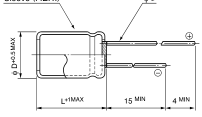
(f 3 : P±0.3)
(mm)
f D 3 4 5 6.3
P 1.0 1.5 2.0 2.5 f d 0.40 0.45 0.45 0.45
- Please refer to page 21 about the end seal configulation.
Dimensions
Type numbering system (Example : 25V 10µF)
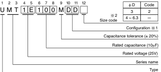
1 Configuration Pb-free leadwire f D Pb-free PET sleeve 3 CD
4 ~ 6.3
DD
2 For f 3mm unit, place size code of 2 to 12th digit.
| V Cap.(µF) Code | 4 | 6.3 | 10 | 16 | 25 | 35 | 50 | ||||||||
| 0G | 0J | 1A | 1C | 1E | 1V | 1H | |||||||||
| 0.1 | 0R1 | 4× 5 | 1.0 | ||||||||||||
| 0.22 | R22 | 4× 5 | 2.6 | ||||||||||||
| 0.33 | R33 | 4× 5 | 3.2 | ||||||||||||
| 0.47 | R47 | 4× 5 | 3.8 | ||||||||||||
| 1 | 010 | 4× 5 | 6.2 (5.9) | ||||||||||||
| 2.2 | 2R2 | 3 × 5 | 7.5 | 4× 5 | 11 (9) | ||||||||||
| 3.3 | 3R3 | 4 × 5 | 11 (9) | 4× 5 | 14 | ||||||||||
| 4.7 | 4R7 | 4× 5 | 13 (10) | 4 × 5 | 15 | 5× 5 | 19 | ||||||||
| 10 | 100 | 4× 5 | 18 (14) | 5× 5 | 23 | 5× 5 | 25 | 6.3× 5 | 30 | ||||||
| 22 | 220 | 4× 5 | 22 | 4× 5 | 22 | 5× 5 | 27 | 5× 5 | 30 | 6.3× 5 | 38 | 6.3× 5 | 48 | ||
| 33 | 330 | 5× 5 | 30 | 5× 5 | 30 | 5× 5 | 35 | 6.3× 5 | 40 | 6.3× 5 | 48 | ||||
| 47 | 470 | 5× 5 | 36 | 5× 5 | 36 | 6.3× 5 | 46 | 6.3× 5 | 50 | Case size φD×L (mm) | Rated ripple | ||||
| 100 | 101 | 6.3× 5 | 60 | 6.3 × 5 | 60 | ||||||||||
Size φ3 × 5 is available for capacitors marked " " Figures in ( ) are for φ 3 product.
Frequency coefficient of rated ripple current
| Frequency | 50 Hz | 120 Hz | 300 Hz | 1 kHz | 10 kHz ~ |
| Coefficient | 0.70 | 1.00 | 1.17 | 1.36 | 1.50 |
Rated Ripple (mArms) at 105°C 120Hz