


 Download PDF
UGE1112AY4 IXYS
Document overview
- PDF pages: 2
Technical content
Page 1
High Voltage Rectifiers
VRRM
Standard
Power Designation
V Types
8000 UGE 1112 AY4 Si-E 3000 / 1300-2.5
Symbol
Conditions
IF(RMS)
IF(AV)M
air self cooling,
Tamb = 45°C - without cooling plate - with colling plate
forced air cooling: v = 3 m/s,
Tamb = 35°C - without cooling plate - with cooling plate
oil cooling,
Tamb = 35°C - without cooling plate - with cooling plate
PRSM
T(vj) = 150°C;
tp = 10 µs
IFSM
non repetitive, 50 c/s (for 60 c/s add 10%) T(vj) = 45°C; tp = 10 ms
T(vj) = 150°C;
tp = 10 ms
Tamb Tstg T(vj) Weight
Symbol
Conditions
IR
T(vj) = 150°C;
VR = VRRM
VF
IF = 7 A T(vj) = 25°C
VTO
T(vj) = 150°C
rT
T(vj) = 150°C
a
f = 50Hz
Md
Data according to IEC 60747-2 IXYS reserve the right to change limits, test conditions and dimensions.
1 - 2
UGE 1112 AY4
VRRM = 8000 V
IF(AV)M =
4.2 A
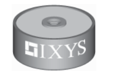
Anode
Cathode
Ratings
Features
- Hermetically sealed Epoxy
7 A
- Use in oil
- Avalanche characteristics
2.0 A 2.5 A
Applications
- X-Ray equipment
- Electrostatic dust precipitators
3.2 A ● Electronic beam welding 4.1 A ● Lasers
- Cable test equipment
4.2 A Advantages
4.2 A
- Simple mounting
2.5 kW
- Improved temperature and power cycling
- Reduced protection circuits
120 A
- Series and parallel operation
100 A
-40...+150
°C
-40...+150
°C 150 °C Dimensions in mm (1 mm = 0.0394")
122
g
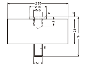
Characteristic Values ≤ 1 mA 6.25
V
4.25
V mΩ 0.215 5 x 9,81
m/s2 8 Nm
© 2003 IXYS All rights reserved
Page 2
UGE 1112 AY4
IFSM
IF
100 s 101
10-3 10-2 10-1
3,0 3,5 4,0 4,5 5,0 5,5 6,0 6,5V
t
VF
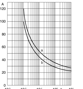
Fig. 2: Characteristics of maximum permissible current
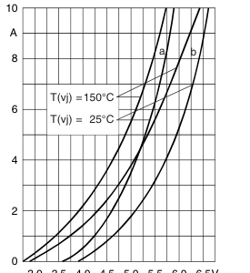
Fig. 1: Forward characteristics
The curves show the non repetitive peak one cycle surge forward
Instantaneous forward current IF as a function of instantaneous forward
current IFSM as a function of time t and serve for rating protective
voltage drop VF for junction temperature T(vj) = 25°C and T(vj) = 150°C a = Mean value characteristic
devices.
b = Limit value characteristic
a = Initial state
T(vj) = 45°C T(vj) = 150°C
b = Initial state
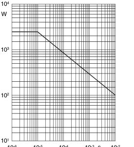
PRSM
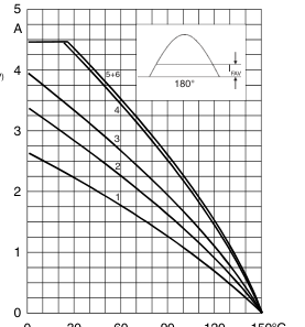
IF(AV)
F6
0 30 60 90 120 150°C
s
10-6 10-5 10-4 10-3 10-2
TA
t
Fig. 4: Load diagramm
Fig. 3: Power loss
Mean forward current IF(AV) of one module for a sine half wave for various
Non repetitive peak reverse power loss PRSM as a function of time t,
cooling modes as a function of the cooling medium temperature Tamb for a
T(vj) = 150°C
resistive load (horizontal mounting).
Cooling modes 1 = air self cooling
without cooling plate
2 = air self cooling
with cooling plate
3 = forced air cooling
without cooling plate
4 = forced air cooling 5 = oil cooling 6 = oil cooling
© 2003 IXYS All rights reserved
with cooling plate without cooling plate with cooling plate
2 - 2