


 Download PDF
UFG1C472MHJ NICHICON
Document overview
- PDF pages: 3
Technical content
Page 1
ALUMINUM ELECTROLYTIC CAPACITORS
FG series
High Grade Standard Type, For Audio Equipment
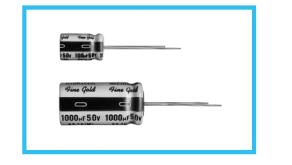
"Fine Gold" MUSE acoustic series suited for high grade
audio equipment, using state of the art etching techniques.
Rich sound in the bass register and clearer high end, most
suited for AV equipment like DVD.
Compliant to the RoHS directive (2002/95/EC).
FG
KZ
FW
High Grade
High Grade
Specifications
| Item | Performance Characteristics |
| Category Temperature Range | –40 to +85°C |
| Rated Voltage Range | 6.3 to 100V |
| Rated Capacitance Range | 0.1 to 10000µF |
| Capacitance Tolerance | ±20% at 120Hz, 20°C |
| Leakage Current | After 1 minute's application of rated voltage, leakage current is not more than 0.01CV or 3 (µA) , whichever is greater. |
| Tangent of loss angle (tan δ) | Measurement frequency : 120Hz at 20°C Rated voltage (V) 6.3 10 16 25 35 50 63 80 100 tan δ (MAX.) 0.22 0.19 0.16 0.14 0.12 0.10 0.09 0.09 0.08 For capacitance of more than 1000µF add 0.02 for every increase of 1000µF. |
| Stability at Low Temperature | Measurement frequency : 120Hz Rated voltage (V) 6.3 10 16 25 35 50 63 80 100 Impedance ratio Z–25°C / Z+20°C 4 3 2 2 2 2 2 2 2 ZT / Z20 (MAX.) Z–40°C / Z+20°C 8 6 4 4 3 3 3 3 3 |
| Endurance | The specifications listed at right Within ±20% of the initial measurement for units of not more than 16V or φ6.3 shall be met when the Capacitance change Within ±15% of the initial measurement for units of not less than 25V or above φ6.3 capacitors are restored to 20°C tan δ 150% or less than the initial specified value after the rated voltage is applied for 1000 hours at 85°C. Leakage current Less than or equal to the initial specified value |
| Shelf Life | After storing the capacitors under no load at 85°C for 1000 hours and then performing voltage treatment based on JIS C 5101-4 clause 4.1 at 20°C, they shall meet the specified values for the endurance characteristics listed above. |
| Marking | Printed with black color letter on gold sleeve. |
| Rated voltage (V) | 6.3 | 10 | 16 | 25 | 35 | 50 | 63 | 80 | 100 |
| tan δ (MAX.) | 0.22 | 0.19 | 0.16 | 0.14 | 0.12 | 0.10 | 0.09 | 0.09 | 0.08 |
| Rated voltage (V) | 6.3 | 10 | 16 | 25 | 35 | 50 | 63 | 80 | 100 | |
| Impedance ratio ZT / Z20 (MAX.) | Z–25°C / Z+20°C | 4 | 3 | 2 | 2 | 2 | 2 | 2 | 2 | 2 |
| Z–40°C / Z+20°C | 8 | 6 | 4 | 4 | 3 | 3 | 3 | 3 | 3 | |
| Capacitance change | Within ±20% of the initial measurement for units of not more than 16V or φ6.3 Within ±15% of the initial measurement for units of not less than 25V or above φ6.3 |
|---|---|
| tan δ | 150% or less than the initial specified value |
| Leakage current | Less than or equal to the initial specified value |
Radial Lead Type
Sleeve (P.E.T.)
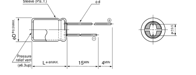
(mm)
| φD | 5 | 6.3 | 8 | 10 | 12.5 | 16 | 18 |
| P | 2.0 | 2.5 | 3.5 | 5.0 | 5.0 | 7.5 | 7.5 |
| φd | 0.6 | 0.6 | 0.6 | 0.6 | 0.8 | 0.8 | 0.8 |
(L < 20) 1.5 (L 20) 2.0
- Please refer to page 20 about the end seal configulation.
Please refer to page 20, 21, 22 about the formed or taped product spec. Please refer to page 4 for the minimum order quantity.
Dimension table in next page.
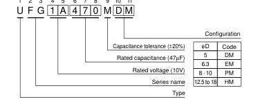
Type numbering system (Example : 10V 47µF)
1 2 3 4 5 6 7 8 9 10 11
CAT.8100B
Page 2
ALUMINUM ELECTROLYTIC CAPACITORS
FG series
Dimensions
| V Cap.(µF) Code | 6.3 | 10 | 16 | 25 | 35 | 50 | |||||||
| 0J | 1A | 1C | 1E | 1V | 1H | ||||||||
| 0.1 | 0R1 | 05× 11 | 1.1 | ||||||||||
| 0.22 | R22 | 05× 11 | 2.4 | ||||||||||
| 0.33 | R33 | 05× 11 | 3.6 | ||||||||||
| 0.47 | R47 | 05× 11 | 5.0 | ||||||||||
| 1 | 010 | 05× 11 | 9.0 | ||||||||||
| 2.2 | 2R2 | 05× 11 | 18 | ||||||||||
| 3.3 | 3R3 | 05× 11 | 22 | ||||||||||
| 4.7 | 4R7 | 05× 11 | 27 | ||||||||||
| 10 | 100 | 05× 11 | 39 | ||||||||||
| 22 | 220 | 05× 11 | 50 | 6.3× 11. | 60 | 6.3× 11. | 65 | ||||||
| 33 | 330 | 05× 11 | 57 | 6.3× 11. | 70 | 6.3× 11. | 75 | 0.08× 11.5 | 93 | ||||
| 47 | 470 | 05× 11 | 60 | 6.3× 11. | 74 | 6.3× 11. | 85 | 00.8× 11.5 | 101 | 0.08× 11.5 | 111 | ||
| 100 | 101 | 6.3× 11. | 99 | 00.8× 11.5 | 128 | 0.08× 11.5 | 140 | 0.10× 12.5 | 176 | 10× 16 | 215 | ||
| 220 | 221 | 0.08× 11.5 | 170 | 0.10× 12.5 | 226 | 10× 16 | 260 | 10× 20 | 320 | 12.5× 200. | 390 | ||
| 330 | 331 | 0.10× 12.5 | 247 | 10× 16 | 309 | 10× 20 | 351 | 12.5× 200. | 446 | 12.5× 200. | 488 | ||
| 470 | 471 | 0.10 × 12.5 | 270 | 10× 16 | 330 | 10× 20 | 406 | 12.5× 20.0 | 476 | 12.5× 250. | 590 | 16× 25 | 650 |
| 1000 | 102 | 10 × 20 | 485 | 12.5× 200. | 601 | 12.5× 250. | 723 | 16× 25 | 854 | 16× 25 | 1060 | 0.16× 31.5 | 1143 |
| 2200 | 222 | 12.5 × 250. | 867 | 16× 25 | 1047 | 16× 25 | 1290 | 0.16× 35.5 | 1570 | 0.18× 35.5 | 1840 | ||
| 3300 | 332 | 16 × 25 | 1135 | 0.16× 31.5 | 1520 | 0.16× 35.5 | 1720 | 18× 40 | 1794 | ||||
| 4700 | 472 | 0.16 × 31.5 | 1431 | 0.16× 35.5 | 1840 | 0.18× 35.5 | 2140 | ||||||
| 6800 | 682 | 0.18 × 35.5 | 1810 | 18× 40 | 2049 | ||||||||
| 10000 | 103 | 18 × 40 | 2100 | ||||||||||
| V Cap.(µF) Code | 63 | 80 | 100 | ||||
| 1J | 1K | 2A | |||||
| 0.1 | 0R1 | 05× 11 | 2.3 | ||||
| 0.22 | R22 | 05× 11 | 5.5 | ||||
| 0.33 | R33 | 05× 11 | 8.0 | ||||
| 0.47 | R47 | 05× 11 | 10 | ||||
| 1 | 010 | 05× 11 | 15 | ||||
| 2.2 | 2R2 | 05× 11 | 22 | ||||
| 3.3 | 3R3 | 05× 11 | 27 | ||||
| 4.7 | 4R7 | 05× 11 | 36 | ||||
| 10 | 100 | 6.3× 11. | 50 | 6.3× 11. | 055 | 0.08× 11.5 | 65 |
| 22 | 220 | 0.08× 11.5 | 85 | 11.8× 11.5 | 100 | 0.10× 12.5 | 110 |
| 33 | 330 | 0.08× 11.5 | 105 | 0.10× 12.5 | 130 | 10× 16 | 150 |
| 47 | 470 | 0.10× 12.5 | 140 | 10× 16 | 170 | 10× 20 | 190 |
| 100 | 101 | 10× 20 | 255 | 12.5× 20.0 | 270 | 12.5× 200 | 300 |
| 220 | 221 | 12.5× 200. | 420 | 12.5× 25.0 | 490 | 16× 25 | 549 |
| 330 | 331 | 12.5× 250. | 541 | .016× 31.5 | 650 | 0.16× 31.5 | 734 |
| 470 | 471 | 16× 25 | 840 | .016× 35.5 | 920 | 0.18× 35.5 | 980 |
| 1000 | 102 | 0.18× 35.5 | 1400 | Case size φD × L (mm) | Rated ripple | ||
Rated ripple current (mArms) at 85°C 120Hz
Frequency coefficient of rated ripple current
| Frequency Cap.(µF) | 50Hz | 120Hz | 300Hz | 1kHz | 10kHz or more |
| 0.1 to 47 | 0.75 | 1.00 | 1.35 | 1.57 | 2.00 |
| 100 to 470 | 0.80 | 1.00 | 1.23 | 1.34 | 1.50 |
| 1000 to 10000 | 0.85 | 1.00 | 1.10 | 1.13 | 1.15 |
CAT.8100B
Page 3
Mouser Electronics
Authorized Distributor
Click to View Pricing, Inventory, Delivery & Lifecycle Information:
Nichicon:
UFG1C472MHJ UFG1A332MHM UFG1C102MHM UFG0J102MPM UFG0J103MHM UFG0J222MHM UFG0J332MHM UFG0J471MPM UFG0J472MHM UFG0J682MHM UFG1A101MEM UFG1A102MHM UFG1A221MPM UFG1A222MHM UFG1A331MPM UFG1A470MDM UFG1A471MPM UFG1A472MHM UFG1A682MHM UFG1C101MPM UFG1C221MPM UFG1C222MHM UFG1C330MDM UFG1C331MPM UFG1C332MHM UFG1C470MEM UFG1C471MPM UFG1C472MHM UFG1E101MPM UFG1E102MHM UFG1E220MDM UFG1E221MPM UFG1E222MHM UFG1E330MEM UFG1E331MPM UFG1E471MHM UFG1H010MDM UFG1H100MDM UFG1H101MPM UFG1H102MHM UFG1H220MEM UFG1H221MHM UFG1H2R2MDM UFG1H330MPM UFG1H331MHM UFG1H3R3MDM UFG1H470MPM UFG1H471MHM UFG1H4R7MDM UFG1HR22MDM UFG1HR33MDM UFG1HR47MDM UFG1V101MPM UFG1V102MHM UFG1V220MEM UFG1V221MPM UFG1V222MHM UFG1V330MEM UFG1V331MHM UFG1V471MHM
UFG1E332MHM UFG1E470MEM UFG1V470MEM UFG1H0R1MDM