Rated voltage (V) 6.3 ~ 100 160 ~ 450 In case of CV 1000 After 1 minute's application of rated voltage, After 1 minute's application of rated voltage, Leakage current not more than 0.03CV or 4 (µA) , whichever is greater. not more than 0.1CV+40 (µA) . After 2 minutes' application of rated voltage, In case of CV > 1000 not more than 0.01CV or 3 (µA) , whichever is greater. After 1 minute's application of rated voltage, not more than 0.04CV+100 (µA) .
tan δ
For capacitance of more than 1000µF, add 0.02 for every increase of 1000µF. Measurement frequency : 120Hz, Temperature : 20°C Rated voltage (V) 6.3 10 16 25 35 50 63 ~ 100 160 ~ 315 350 ~ 450 tan δ (MAX.) 0.24 0.20 0.16 0.14 0.12 0.10 0.08 0.20 0.25
After 2000 hours' application of rated voltage Capacitance change Within ±20% of initial value at 85°C, capacitors meet the characteristic tan δ 200% or less of initial specified value requirements listed at right. Leakage current Initial specified value or less
Shelf Life
After leaving capacitors under no load at 85°C for Capacitance change Within ±20% of initial value 1000 hours, they meet the characteristic tan δ 200% or less of initial specified value requirements at right. Leakage current Initial specified value or less
Marking
Printed with white color letter on black sleeve.
Axial Lead Type Type numbering system (Example : 10V 330µF) 1 2 3 4 5 6 7 8 9 10 11 Pressure relief vent T V X 1 A 3 3 1 M A D Sleeve (P.E.T.) (φ10up) φ d Sealing rubber packing Configuration +0.5MAX Capacitance tolerance (±20%) Rated Capacitance (330µF) φD Rated voltage (10V) 35MIN L+ MAX 35MIN Series name Type Configuration (φD < 10) 1 φD 5 ~ 13 16 ~ 1(m 8m) φ D P Pb b- -f fr re ee e l Pe Ead Tw si lr ee eve S PVn C-P sb le f ein vi es h (ce od n tl ae ina id nw g i Pre b) α 5 ~ 8 AD AA (φD 10) 2 φd 0.6 0.8 10 ~ 18 CD CA
6.3 ~ 100
160 ~ 450
After 1 minute's application of rated voltage, not more than 0.03CV or 4 (µA) , whichever is greater. After 2 minutes' application of rated voltage, not more than 0.01CV or 3 (µA) , whichever is greater.
In case of CV 1000 After 1 minute's application of rated voltage, not more than 0.1CV+40 (µA) . In case of CV > 1000 After 1 minute's application of rated voltage, not more than 0.04CV+100 (µA) .
Please contact to us if other configurations are required.
Please refer to page 19, 20, 21 about the formed or taped product spec.
Please refer to page 3 for the minimum order quantity.
Dimension table in next page.
CAT.8100T
Page 2
ALUMINUM ELECTROLYTIC CAPACITORS
VX (02 type) series
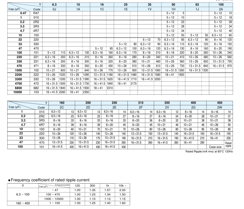
Dimensions
φ D ×L (mm)
CAT.8100T
Selected Specification
Nichicon corporation TVX1A331MAD overview.
Overview
TVX1A331MAD is listed in the IC category. Available datasheets include documents from Nichicon corporation. DigiCamel provides a local PDF and searchable HTML technical text for online reference.



 Download PDF