

 Download PDF
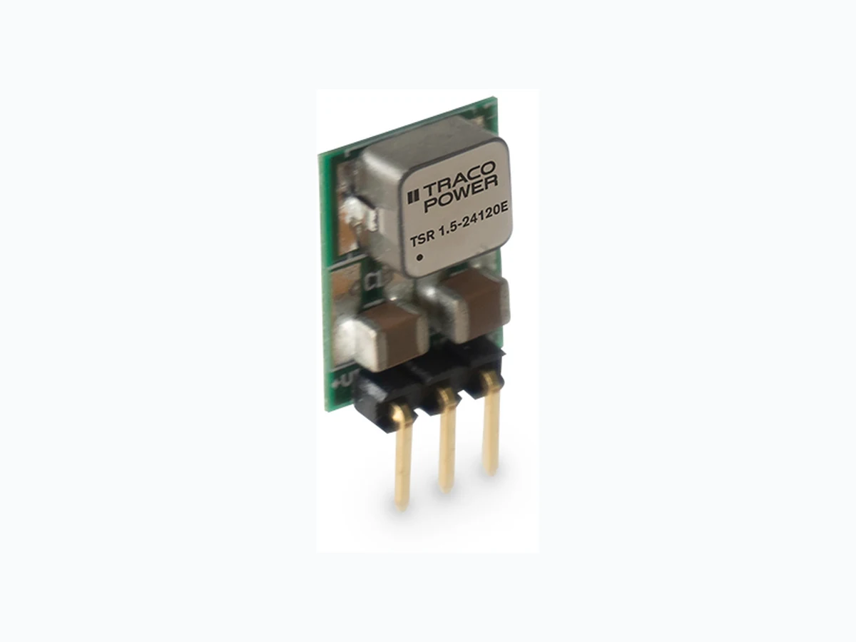
TSR1-5E TRACOPOWER
Document overview
- PDF pages: 4
Technical content
Page 1
Non-Isolated DC/DC Converter (POL)
- Highly cost efficient design
- Pin compatible with TO-220 package 78xx linear regulators
- Operation temperature range –40°C to +85°C without derating
- Efficiency up to 97%
The TSR 1.5E is a 1.5 Ampere step-down switching regulator series and a
- Wide input operating range 7-36 VDC drop-in replacement for inefficient LM78xx linear regulators. This series comes
in a compact SIP-3 open frame package and complements our existing POL
- Short circuit protection
portfolio with a series focusing strongly on a cost efficient design while main-
- Excellent line / load regulation
taining our quality standards. There are 3 output voltages available: 3.3, 5.0 and 12VDC. The effective design allows full load operation up to +85°C ambi-
- 3-year product warranty
ent temperature without the need of any heat sink or forced cooling. The TSR 1.5E switching regulators provide other significant features over linear regulators, i.e. better output accuracy, lower standby current and no requirement of external capacitors. The TSR 1.5E series offers a broad application range in many environments and is especially suited for high volume projects where the series will help to reduce production cost by delivering not only a highly cost ef- ficient but also reliable solution.
Models
| Order Code | Output Current max. | Input Voltage Range | Output Voltage nom. | Efficiency typ. |
|---|---|---|---|---|
| TSR 1.5-2433E TSR 1.5-2450E TSR 1.5-24120E | 1'500 mA | 7 - 36 VDC (24 VDC nom.) | 3.3 VDC 5 VDC 12 VDC | 93 % (at Vin min.) 95 % (at Vin min.) 97 % (at Vin min.) |
| 1'000 mA | 15 - 36 VDC (24 VDC nom.) |
Note - For input voltage higher 24 VDC an input capacitor of 22 µF is required
Page 1 / 4
Page 2
Input Specifications
Input Current
- At no load
Surge Voltage Input Inrush Current
Recommended Input Fuse
Input Filter
Output Specifications
Voltage Set Accuracy Regulation
- Input Variation (Vmin - Vmax) - Load Variation (25 - 100%)
Ripple and Noise (20 MHz Bandwidth)
Capacitive Load
Minimum Load Temperature Coefficient Hold-up Time
Start-up Time Short Circuit Protection Output Current Limitation Transient Response
- Peak Variation
- Response Time
EMC Specifications
EMI Emissions
- Conducted Emissions
- Radiated Emissions
General Specifications
Relative Humidity Temperature Ranges
- Operating Temperature - Case Temperature - Storage Temperature
Power Derating
- High Temperature
Over Temperature
- Protection Mode
Protection Switch Off
- Measurement Point
Cooling System Altitude During Operation
15 mA max. 40 VDC max. (1 s max.) 70 A typ. (12 Vout model) 30 A typ. (other models) 2'000 mA (fast acting) (The need of an external fuse has to be assessed in the final application.) Internal Capacitor
±4% max. (at 50% load) 0.7% max. 0.7% max.
3.3 Vout models: 40 mVp-p max. (w/ 47 µF) 5 Vout models: 75 mVp-p max. (w/ 47 µF) 12 Vout models: 75 mVp-p max. (w/ 47 µF) 3.3 Vout models: 1'200 µF max. 5 Vout models: 660 µF max. 12 Vout models: 470 µF max.
Not required ±0.02 %/K max. 40 µs min. (3.3 Vout model) 160 µs min. (5 Vout model) 1'400 µs min. (12 Vout model) 2.1 ms max. Continuous, Automatic recovery 200 - 500% of Iout max. 70 mV max. (50% to 100% Load Step) (3.3 Vout model) 90 mV max. (50% to 100% Load Step) (5 Vout model) 130 mV max. (50% to 100% Load Step) (12 Vout model) 75 µs typ. (50% to 100% Load Step)
EN 55032 class A (with external filter) EN 55032 class B (with external filter) EN 55032 class A (with external filter) EN 55032 class B (with external filter)
External filter proposal: www.tracopower.com/overview/tsr1-5e
95% max. (non condensing) –40°C to +85°C +130°C max. –55°C to +125°C Depending on model
See application note: www.tracopower.com/overview/tsr1-5e
130°C to 140°C (Automatic recovery at 130°C typ.) Internal IC temperature Natural convection (20 LFM) 2'000 m max.
All specifications valid at nominal voltage, resistive full load and +25°C after warm-up time, unless otherwise stated.
Page 2 / 4
Page 3
Switching Frequency
Insulation System Reliability
- Calculated MTBF
Washing Process Pin Material Pin Foundation Plating Pin Surface Plating Housing Type Mounting Type Connection Type Footprint Type Soldering Profile
Weight Thermal Impedance
- Case to Ambient
Environmental Compliance - REACH Declaration
- RoHS Declaration
Supporting Documents
Overview Link (for additional Documents)
320 - 500 kHz (PWM) 410 kHz typ. (PWM) Non-isolated 16'000'000 h (12 Vout model) 6'800'000 h (other models) (MIL-HDBK-217F, ground benign) Not allowed (non-hermetical product) Copper Alloy Nickel (0.5 µm min.) Gold (10 nm min.), bright Open Frame PCB Mount THD (Through-Hole Device) SIP3 Wave Soldering 265 °C / 5 s max. 2 g 60 K/W typ. www.tracopower.com/info/reach-declaration.pdf REACH SVHC list compliant REACH Annex XVII compliant www.tracopower.com/info/rohs-declaration.pdf Exemptions: 7a, 7c-I (RoHS exemptions refer to the component concentration only, not to the overall concentration in the product (O5A rule). The SCIP number is provided on request.)
www.tracopower.com/overview/tsr1-5e
All specifications valid at nominal voltage, resistive full load and +25°C after warm-up time, unless otherwise stated.
Page 3 / 4
Page 4
Outline Dimensions
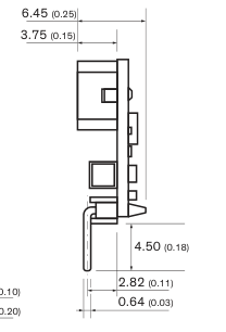
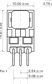
All dimensions in mm (inch) General Tolerances: ±0.5 (±0.02) Pin Pitch Tolerance: ±0.25 (±0.01)
© Copyright 2022 Traco Electronic AG
| Pin Assignment | |
| Pin | Function |
| 1 | + Vin |
| 2 | Common Ground |
| 3 | + Vout |
Specifications can be changed without notice.
Rev. November 30, 2022
Page 4 / 4