

 Download PDF
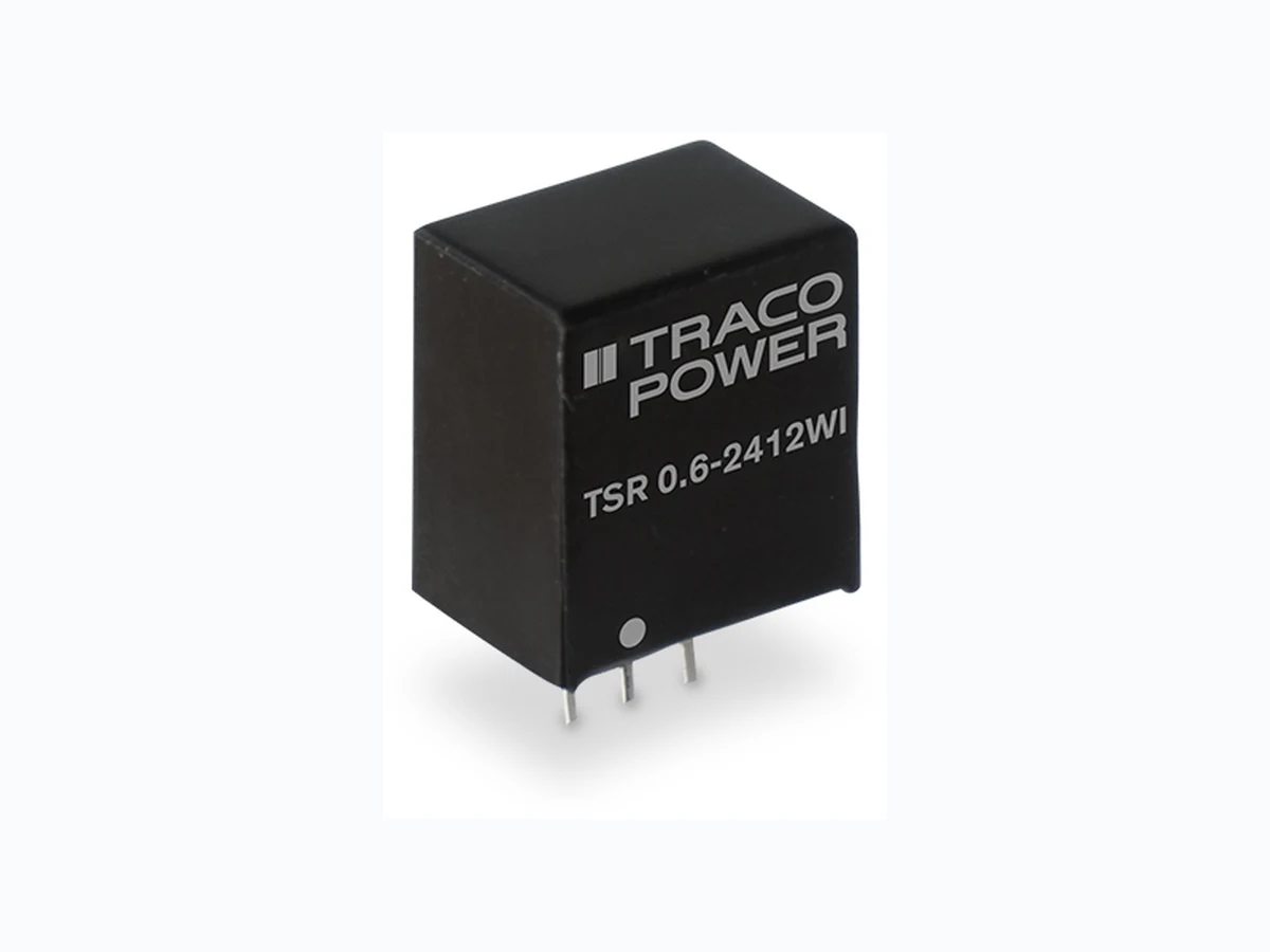
TSR0-6WI TRACOPOWER
Document overview
- PDF pages: 5
Technical content
Page 1
Non-Isolated DC/DC Converter (POL)
- Ultra wide 8:1 input voltage range: 9-72 VDC
- Covers a majority of standard bus- and battery voltages
- Up to 94% efficiency - No heatsink required
The TSR 0.6WI is a non-isolated POL converter series with an ultra wide 8:1 in-
- Pin compatible with LMxx linear
put voltage range which comes in a standard SIP-3 package. Covering the ma-
regulators (SIP-3)
jority of standard bus- and battery voltages this POL converter is a versatile so-
- Operating temperature range
lution for many applications in distributed power systems where different input
-40 to +85°C
voltages have to be handled. Being able to use the same converter in many different situations effectively reduces the bill of material (BOM) of a given appli-
- Low standby current
cation. A high efficiency of up to 94% allows for an operating temperature
- Excellent line/load regulation
range of -40 to +85°C (up to 80°C without derating) and makes them excellent drop-in replacements for less efficient LMxx linear regulators. With 0.6A max.
- Protection against short circuit,
output current and standard features such as low standby current, precise reg-
overvoltage and overtemperature
ulation and protection against short circuit, overvoltage and overload the TSR
- 3-year product warranty
0.6WI is suitable for many battery and distributed power applications.
Models
| Order Code | Output Current max. | Input Voltage Range | Output Voltage nom. | Efficiency typ. |
|---|---|---|---|---|
| TSR 0.6-4833WI TSR 0.6-4850WI TSR 0.6-4865WI TSR 0.6-4890WI TSR 0.6-48120WI TSR 0.6-48150WI TSR 0.6-48240WI | 600 mA | 9 - 72 VDC (48 VDC nom.) | 3.3 VDC 5 VDC 6.5 VDC 9 VDC 12 VDC 15 VDC 24 VDC | 85 % (at 24 Vin) 89 % (at 24 Vin) 91 % (at 24 Vin) 92 % (at 24 Vin) 93 % (at 24 Vin) 94 % (at 24 Vin) 94 % (at 48 Vin) |
| 14 - 72 VDC (48 VDC nom.) | ||||
| 17 - 72 VDC (48 VDC nom.) | ||||
| 20 - 72 VDC (48 VDC nom.) | ||||
| 400 mA | 33 - 72 VDC (48 VDC nom.) |

Note - It is recommended to use an external input filter, please refer to application note: www.tracopower.com/overview/tsr0-6wi
Page 1 / 5
Page 2
Input Specifications
Input Current
- At no load
Recommended Input Fuse
Input Filter
Output Specifications
Voltage Set Accuracy Regulation
- Input Variation (Vmin - Vmax) - Load Variation (10 - 100%)
Ripple and Noise (20 MHz Bandwidth)
Capacitive Load Minimum Load Temperature Coefficient Start-up Time
Short Circuit Protection Output Current Limitation Transient Response
- Peak Variation - Response Time
General Specifications
Relative Humidity Temperature Ranges
- Operating Temperature - Case Temperature - Storage Temperature
Power Derating
- High Temperature
Over Temperature
- Protection Mode
Protection Switch Off
- Measurement Point
Cooling System Switching Frequency
Insulation System Reliability
- Calculated MTBF
3 mA typ.
3.3 Vout models: 800 mA (slow blow) 5 Vout models: 800 mA (slow blow) 6.5 Vout models: 1'000 mA (slow blow) 9 Vout models: 1'000 mA (slow blow) 12 Vout models: 1'000 mA (slow blow) 15 Vout models: 1'000 mA (slow blow) 24 Vout models: 800 mA (slow blow)
(The need of an external fuse has to be assessed in the final application.)
See application note: www.tracopower.com/overview/tsr0-6wi
(Recommended external input filter proposal)
±2.5% max. 0.9% max. 0.6% max.
3.3 Vout models: 50 mVp-p typ. 5 Vout models: 50 mVp-p typ. 6.5 Vout models: 50 mVp-p typ. 9 Vout models: 50 mVp-p typ. 12 Vout models: 50 mVp-p typ. 15 Vout models: 50 mVp-p typ. 24 Vout models: 75 mVp-p typ.
100 µF max. Not required ±0.02 %/K max. 50 ms typ. (24 Vout model) 25 ms typ. (other models) Continuous, Automatic recovery 200% typ. of Iout max. 90 mV typ. / 180 mV max. (50% Load Step) 150 µs typ. / 250 µs max. (50% Load Step)
95% max. (non condensing) –40°C to +85°C +105°C max. –55°C to +125°C Depending on model
See application note: www.tracopower.com/overview/tsr0-6wi
165°C typ. (Automatic recovery) Internal IC temperature Natural convection (20 LFM) 117 - 243 kHz (PWM) (3.3 Vout model) 130 - 270 kHz (PWM) (5 Vout model) 163 - 338 kHz (PWM) (6.5 Vout model) 195 - 405 kHz (PWM) (9 Vout model) 247 - 513 kHz (PWM) (12 Vout model) 293 - 608 kHz (PWM) (15 Vout model) 416 - 864 kHz (PWM) (24 Vout model) Non-isolated 18'160'000 h (MIL-HDBK-217F, ground benign)
All specifications valid at nominal voltage, resistive full load and +25°C after warm-up time, unless otherwise stated.
Page 2 / 5
Page 3
Washing Process
Allowed (hermetical product)
See Cleaning Guideline:
Environment
- Vibration - Mechanical Shock - Thermal Shock
Housing Material Potting Material Pin Material Pin Foundation Plating Pin Surface Plating Housing Type Mounting Type Connection Type Footprint Type Soldering Profile Weight Environmental Compliance - REACH Declaration
- RoHS Declaration
Supporting Documents
Overview Link (for additional Documents)
www.tracopower.com/info/cleaning.pdf MIL-STD-810F MIL-STD-810F MIL-STD-810F Non-conductive Plastic (UL 94 V-0 rated) Epoxy (UL 94 V-0 rated) Brass Nickel (1 - 2 µm) Tin (3 - 5 µm), matte Plastic Case PCB Mount THD (Through-Hole Device) SIP3 Wave Soldering 3 g www.tracopower.com/info/reach-declaration.pdf REACH SVHC list compliant REACH Annex XVII compliant www.tracopower.com/info/rohs-declaration.pdf Exemptions: 7a, 7c-I (RoHS exemptions refer to the component concentration only, not to the overall concentration in the product (O5A rule). The SCIP number is provided on request.)
www.tracopower.com/overview/tsr0-6wi
All specifications valid at nominal voltage, resistive full load and +25°C after warm-up time, unless otherwise stated.
Page 3 / 5
Page 4
Outline Dimensions
Standard: Vertical mounting
12.0 (0.47)
| Pinout | |
| Pin | Function |
| 1 | +Vin |
| 2 | GND |
| 3 | +Vout |
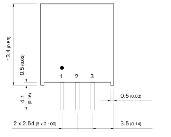
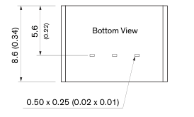
Dimensions in mm (inch) Tolerances: x.xx ±0.5 (±0.02) Tolerances: x.xxx ±0.25 (±0.01) Pin dimension tolerances: ±0.10 (±0.04)
All specifications valid at nominal voltage, resistive full load and +25°C after warm-up time, unless otherwise stated.
Page 4 / 5
Page 5
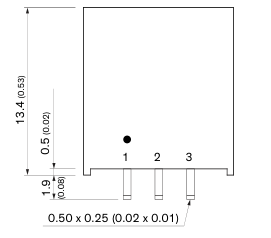
Optional: Horizontal mounting
| Pinout | |
| Pin | Function |
| 1 | +Vin |
| 2 | GND |
| 3 | +Vout |
12.0 (0.47)
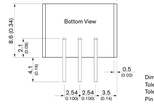
Dimensions in mm (inch) Tolerances: x.xx ±0.5 (±0.02) Tolerances: x.xxx ±0.25 (±0.01) Pin dimension tolerances: ±0.10 (±0.04)
© Copyright 2022 Traco Electronic AG
Specifications can be changed without notice.
Rev. November 30, 2022
Page 5 / 5