

 Download PDF
TRX10GDL0610 FCI-CONNECTOR
Document overview
- PDF pages: 12
Technical content
Page 1
TRANCEIVERS


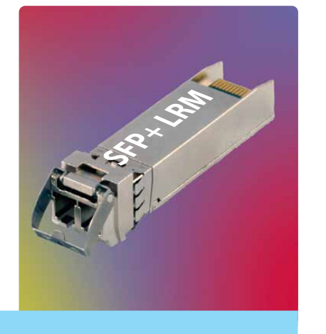
10GBd SFP+ 1310nm LRM Linear Transceiver TRX10GDL0610
APPLICATIONS
10G Ethernet 10GBASE-LRM
MergeOptics SFP+ transceiver TRX10GDP0610 is an optical transceiver module for transmission over legacy multimode fibers. It complies with SFP+ MSA specifications (SFF-8431 and SFF-8432) and 10GBASE-LRM per IEEE 802.3aq. It is RoHS 6/6 complaint per Directive 2002/95/EC and laser class 1 safety compliant per IEC/CDRH. The sub watt power consumption and the excellent EMI performance allow system design with high port density.
SUPPORTED STANDARDS
Application
Standard Data Rate
10G Ethernet
IEEE 802.3aq 10GBASE-LRM
10.3125GBd
FEATURES & BENEFITS
Compliant to SFP+ Electrical MSA SFF-8431 Compliant to SFP+ Mechanical MSA SFF-8432 Ethernet 10GBase-LRM compliant Data rate transparent from 9.95Gbps to 11.3Gbps Support I2C for serial transceiver ID and digital diagnostic monitoring per SFF-8472. Transmission distance up to 220m (MO1 fiber) Low power consumption: 0.8W (Typ.) 0°C to +70°C case operating temperature range 1310nm DFB laser

Page 2
TABLE OF CONTENTS
Table of Contents
2
Functional Description
3
Electrical Characteristics
4 4
Absolute Maximum Ratings
4
Recommended Operating Conditions
4
Low Speed Characteristics
5
SFI Module Transmitter Input Characteristics SFI Module Receiver Output Characteristics
5
Optical Characteristics
6 6
General Parameters
6
Optical Transmitter
6
Optical Receiver Application Information
7 7
Connector Pinout
7
Electrical Pin Definition
8
Application Schematics
9
Interfacing the Transceiver
Digital Diagnostic Monitoring
9
Digital Diagnostic Monitoring Accuracy
9
Module Outline
10
Ordering Information
10
Regulatory Compliance
11 11
Module Safety
11
ESD & Electromagnetic compatibility Eye Safety
11
Sales Contacts
12
Page 3
FUNCTIONAL DESCRIPTION
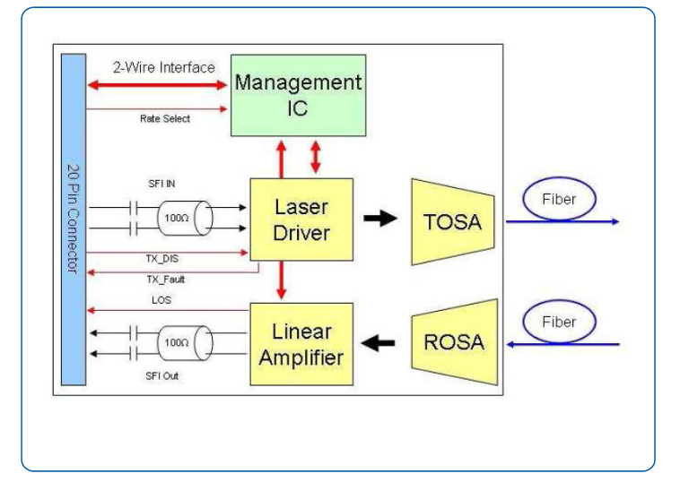
The Transceiver convert information from electrical to optical format, and back again, at different data rates depending upon the chosen standard.
The transmit path consists of an AC coupled 100 ohm differentially terminated driver coupled to a highly reliable 1310nm DFB. The laser output may be disabled by pulling the TX_DISABLE line high. The laser is also disabled if this line is left floating, as it is pulled high inside the transceiver. A fault condition is raised upon detection of an abnormal laser state. The RATE-SELECT is not implemented in the LRM module.
The receiver path consists of a ROSA (receiver optical sub-assembly) for optical electrical conversion, followed by a linear amplifier to boost the electrical signal. A LOSS_OF_SIGNAL (LOS) status line is provided to facilitate easy link detection. The receiver RATE_SELECT pin is not used by the transceiver.
Complete digital optical monitoring is implemented in compliance to SFF-8472 and made accessible via the 2-wire interface providing real time information about all important module parameters and status in- formation.
Page 4
ELECTRICAL CHARACTERISTICS
Absolute Maximum Ratings
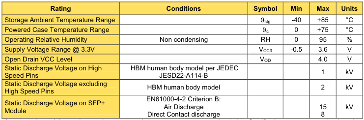
Any stress beyond the maximum ratings may result in permanent damage to the device. Specifications are guaranteed only under recommended operating conditions.
Recommended Operating Conditions
| Parameter | Conditions | Symbol | Min | Typ | Max | Units |
|---|---|---|---|---|---|---|
| Operating Case Temperature Range | altitude of < 3km | ϑ Case | 0 | +70 | °C | |
| Power Supply Voltage @ 3.3V | V CC3 | 3.135 | 3.300 | 3.465 | V | |
| DC Common Mode Voltage | V CM | 0 | 3.6 | V |
Low Speed Characteristics
| Parameter | Conditions | Symbol | Min | Typ | Max | Units |
|---|---|---|---|---|---|---|
| Supply Current Transmitter | @ V CCTX | I VCCTX | 150 | mA | ||
| Supply Current Receiver | @ V CCRX | I VCCRX | 85 | mA | ||
| Total Supply Current | I + VCCTX I VCCRX | 240 | 290 | mA | ||
| Power Consumption | 0.73 | 1.0 | W | |||
| TX_Fault, RX_LOS, SCL, SDA | Host Vcc Range 2V – 3.46V | V OL | 0 | 0.4 | V | |
| V OH | Host_ Vcc – 0.5 | Host_ Vcc + 0.3 | ||||
| TX_Dis | Low Voltage TTL | V IL | -0.3 | 0.8 | ||
| V IH | 2.0 | VccT + 0.3 | ||||
| SCL, SDA | Host Vcc Range 3.14V – 3.46V | V IL | -0.3 | VccT* 0.3 | ||
| V IH | VccT* 0.7 | VccT + 0.5 | ||||
| V OL | 0.0 | 0.4 | ||||
| V OH | Host_ Vcc – 0.5 | Host_ Vcc + 0.3 |
Page 5
FUNCTIONAL DESCRIPTION
SFI Module Transmitter Input Characteristics
| Parameter | Conditions | Symbol | Min | Typ | Max | Units |
|---|---|---|---|---|---|---|
| Supported Data Rate | V ID | 10.3125 | Gbd | |||
| Reference Differential Input Impedance | Z d | 100 | Ω | |||
| Input AC Common Mode Input Voltage | 0 | 25 | mV (RMS) | |||
| Differential Input Voltage Swing | V ID | 180 | 700 | mV | ||
| Differential Input S-parameter | 0.01 – 3.9GHz | SDD11 | -10 | dB | ||
| 3.9 – 11.1GHz | See 1) | See 1) | dB | |||
| Differential to Common Mode Conversion 2) | 0.01 – 11.1Ghz | SCD11 | -10 | dB | ||
| Total Jitter | TJ | 0.28 | UI(p-p) | |||
| Data Dependant Jitter | DDJ | 0.1 | UI(p-p) | |||
| Uncorrelated Jitter | UJ | 0.023 | RMS | |||
| Eye Mask | See SFP+ MSA | X1 | 0.14 | UI | ||
| X2 | 0.35 | UI |
1) Differential Return Loss given by equation SDD11(dB) = -8+13.33 Log10(f/5.5), with f in GHz 2) Common mode reference impedance is 25 . Differential to common mode conversion relates to generation of EMI
SFI Module Receiver Output Characteristics
| Parameter | Conditions | Symbol | Min | Typ | Max | Units |
|---|---|---|---|---|---|---|
| Supported Data Rate | 10.3125 | Gbd | ||||
| Reference Differential Output Impedance | Z d | 100 | Ω | |||
| Termination Mismatch | d | 5 | % | |||
| Output AC Common Mode Voltage | 15 | mV (RMS) | ||||
| Differential Output Amplitude | R = 100Ohm, Differential Load | V OSPP | 180 | 600 | mV | |
| Differential Output S-parameter | 0.01 – 3.9GHz | SDD22 | -10 | dB | ||
| 3.9 – 11.1GHz | See 1) | dB | ||||
| Common Mode Output Return Loss2) | 0.01 – 6.5GHz | SCC22 | -7 | dB | ||
| 6.5 – 11.1GHz | -3 | dB | ||||
| Receiver Waveform Distortion Penalty | dWDP | 1.5 | dB |
1) Return Loss given by equation Sxx22(dB) = -8+13.33 Log10(f/5.5), with f in GHz 2) Common mode reference impedance is 25 . Common mode return loss helps absorb reflection and noise improving EMI
Page 6
OPTICAL CHARACTERISTICS
General Parameters
| Parameter | Conditions | Min Modal Bandwidth (MHz*km) | Symbol | Min | Max | Units |
|---|---|---|---|---|---|---|
| Operating Range | 62.5 µm MO1 MMF 50 µm MO2 MMF 50 µm MO3 MMF | 500 | l OP | 220 | m |
Optical Transmitter
| Parameter | Conditions | Symbol | Min | Typ | Max | Units |
|---|---|---|---|---|---|---|
| Nominal Wavelength | λ TRP | 1290 | 1310 | 1330 | nm | |
| Side Mode Suppression Ratio | SMSR | 30 | dB | |||
| Average Launch Power | P avg | -6.5 | 0.5 | dBm | ||
| Optical Modulation Amplitude | 10.3125GBd Ethernet | P OMA | -4.5 | 1.5 | dBm | |
| Extinction Ratio | ER | 3.5 | 5.0 | dB | ||
| Relative Intensity Noise | RIN | -128 | dB/Hz |
Optical Receiver
| Parameter | Conditions | Symbol | Min | Typ | Max | Units |
|---|---|---|---|---|---|---|
| Maximum Input Power | P MAX | 0.5 | dBm | |||
| Center Wavelength | λ C | 1290 | 1310 | 1355 | nm | |
| Overload | P Sat | 1.5 | dBm | |||
| Stressed Receiver Sensitivity | OMA, PRBS 231-1, BER < 1*10-12 @10.3125GBd | P IN | -6.5 | dBm | ||
| Stressed Receiver Sensitivity Symmetrical Test | P IN | -6 | dBm | |||
| Loss of Signal | P av_as | -25 | -16 | dBm | ||
| P av_deas | -14.5 | -13 | ||||
| Loss of Signal Hysteresis | 0.5 | 1.5 | dBm |
Note: The specified characteristics are met within the recommended range of operating. Unless otherwise noted typical data are quoted at nominal voltages and +25°C ambient temperature.
Page 7
APPLICATION INFORMATION
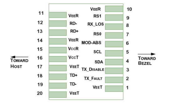
Connector Pinout
Electrical Pin Definition
| PIN | Logic | Symbol | Name / Description | Note |
|---|---|---|---|---|
| 1 | VeeT | Module Transmitter Ground | 1 | |
| 2 | LVTTL-O | TX_Fault | Module Transmitter Fault | |
| 3 | LVTTL-I | TX_Dis | Transmitter Disable; Turns off transmitter laser output | |
| 4 | LVTTL-I | SCL | 2-Wire Serial Interface Clock | 2 |
| 5 | LVTTL-I/O | SDA | 2-Wire Serial Interface Data Line | 2 |
| 6 | MOD_DEF0 | Module Definition, Grounded in the module | ||
| 7 | LVTTL-I | RS0 | No function implemented | |
| 8 | LVTTL-O | RX_LOS | Receiver Loss of Signal Indication Active LOW | |
| 9 | LVTTL-I | RS1 | No function implemented | |
| 10 | VeeR | Module Receiver Ground | 1 | |
| 11 | VeeR | Module Receiver Ground | 1 | |
| 12 | CML-O | RD- | Receiver Inverted Data Output | |
| 13 | CML-O | RD+ | Receiver Data Output | |
| 14 | VeeR | Module Receiver Ground | 1 | |
| 15 | VccR | Module Receiver 3.3 V Supply | ||
| 16 | VccT | Module Receiver 3.3 V Supply | ||
| 17 | VeeT | Module Transmitter Ground | 1 | |
| 18 | CML-I | TD- | Transmitter Inverted Data Input | |
| 19 | CML-I | TD+ | Receiver Non-Inverted Data Output | |
| 20 | VeeT Module Transmitter Ground | 1 | ||
- Module ground pins GND are isolated from the module case. 2. Shall be pulled up with 4.7K-10Kohms to a voltage between 3.15V and 3.45V on the host board.
Page 8
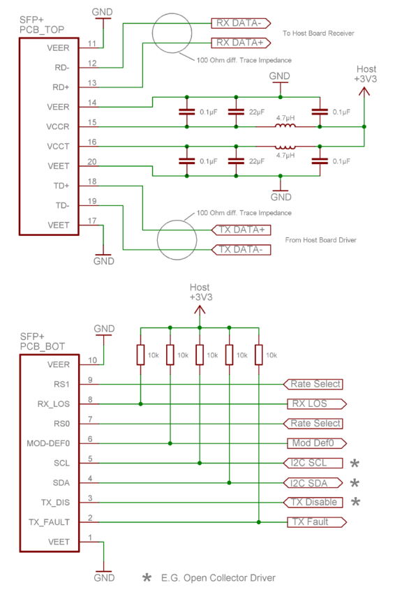
APPLICATION SCHEMATICS
Recommended electrical connections to transceiver are shown below.
Page 9
INTERFACING THE TRANSCEIVER
Communication is d one b y a serial 2 -wire interface similar to t he I 2C b us p rotocol. A s described in t he document SFF-8472 there are two distinct address spaces:
| Base Address A0(hex) | |
| Byte Address | Content |
| 0- 95 | Serial Transceiver ID as defined in SFP MSA |
| 96 -1 27 | MergeOptics Specific |
| 128- 255R | eserved |
| Base Address A2(hex) | |
| Byte Address | Content |
| 0- 55 | Alarm & Warnings thresholds & limits |
| 56 -9 5 | External calibration constants (not used) |
| 96 –1 19 | Values from real time diagnostic monitoring |
| 120– 127N | ot used |
| 128– 247 | Customer specific, writable area |
| 248- 255N | ot used |
Memory map details are described in a separate app note.
Digital Diagnostic Monitoring
Transceivers offer the ability to monitor important module parameter during operation. The five parameters listed below are continuously monitored for getting information about the current module status. All data is calibrated internally; there is no need for external post processing.
Temperature Internally measured temperature data is represented as two’s complement of a signed 16-bit value in increments of 1/256 °C over a range of -40 to +100°C. Accuracy is better than +/-3%.
Supply Voltage (VCC) Internally measured supply voltage. Represented as a 16-bit unsigned integer with the voltage defined as the full 16 bit value (0 – 65535) with LSB equal to 100 Volt, which yields to a total range of 0 to +6.55 Volts. Accuracy is better than +/-3%.
Laser Bias Current VCSEL bias current. Represented as a 16 bit unsigned integer with the current defined as the full 16-bit value (0 – 65535) with LSB equal to 2 A, valid range is 0 to 20 mA. Accuracy is better than +/-10%.
Optical Transmitter Power TX output power measurement is based on internal monitor diode feedback. Represented as a 16-bit unsigned integer with the power defined as the full 16 bit value (0 – 65535) with LSB equal to 0.1 W. Accuracy is better than +/-3dB over a range of Pavmin to Pavmax.
Receiver Optical Power RX input power measurement is based on photodiode diode current. Represented as a 16-bit unsigned integer with the power defined as the full 16 bit value (0 – 65535) with LSB equal to 0.1 W. Accuracy is better than +/-3dB over a range of -12dBm to -1dBm.
Digital Diagnostic Monitoring Accuracy
| Parameter | Conditions | Symbol | Min | Typ | Max | Units |
|---|---|---|---|---|---|---|
| Internally measured transceiver temperature | supply voltage 3.30V ± 5% transceiver temperature 0 to 70°C | ∆T | -3 | ±1 | 3 | °C |
| Internally measured supply voltage | ∆V | -0.1 | 0.1 | V | ||
| Laser bias current | ∆I | -10 | 10 | % | ||
| TX output power | ∆P Tx | -2 | ±1 | 2 | dBm | |
| RX input power | ∆P Rx | -2 | ±1 | 2 | dBm |
Note: min and max specs are met over specified full temperature and voltage range. Typ shows typical values at room temperature and nominal supply voltage.
Page 10
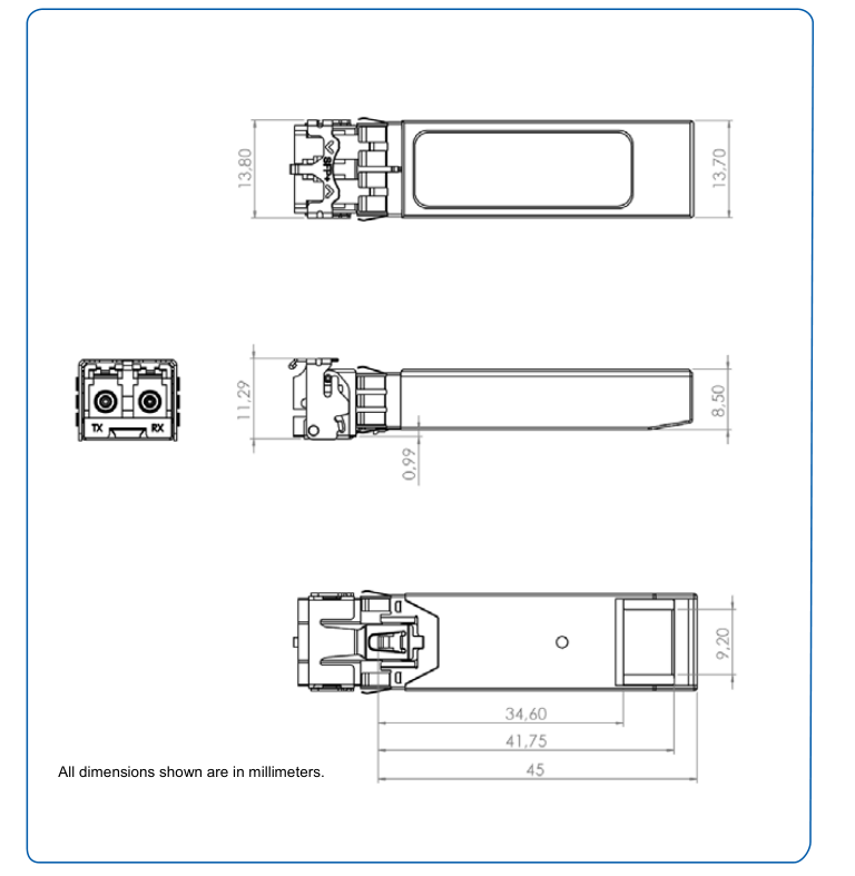
MODULE OUTLINE
ORDERING INFORMATION
Page 11
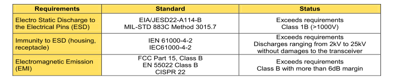
REGULATORY COMPLIANCE


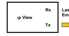
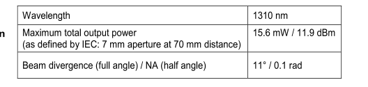
EYE SAFETY
Page 12
Contact info
EUROPE
FCI Deutschland GmbH Wernerwerkdamm 16 13629 Berlin, Germany Ph: +49 30 750 795 00 Fax: +49 30 386 37 54
AMERICAS
MergeOptics 1551 McCarthy Blvd, Suite 116 Milpitas, CA 95035 USA Phone: 408-493-9970
More information about FCI’s complete range of High Speed Input/Output products can be found on www.fciconnect.com/hsio
For more information about e-catalog or FCI sales offices, headquarters, agents and local distributors,
visit www.fciconnect.com