
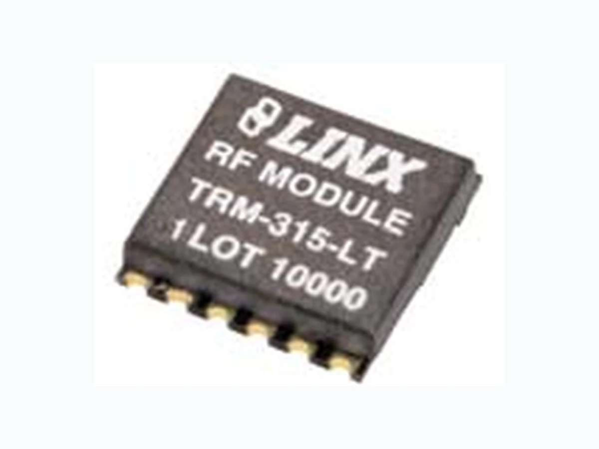
TRM-315-LT ETC2
Document overview
- Manufacturer or author: Provided By www.digicamel.com(FREE DATASHEET DOWNLOAD SITE)
- PDF pages: 13
Technical content
DESCRIPTION
The LT Series transceiver is ideal for the bi- directional wireless transfer of serial data, control, or command information in the favorable 260-470MHz band. The transceiver is capable of generating +10dBm into a 50-ohm load and achieves an outstanding typical sensitivity of -112dBm. Its advanced synthesized architecture delivers outstanding stability and frequency accuracy, and minimizes the effects of antenna pulling. When paired, the transceivers form a reliable wireless link that is capable of transferring data at rates of up to 10,000bps over distances of up to 3,000 feet. Applications operating over shorter distances or at lower data rates will also benefit from increased link reliability and superior noise immunity. Housed in a tiny reflow-compatible SMD package, the transceiver requires no external RF components (except an antenna), which greatly simplifies integration and lowers assembly costs. LT SERIES TRANSCEIVER MODULE DATA GUIDE WIRELESS MADE SIMPLE® Revised 2/28/08 Figure 1: Package Dimensions 0.125" 0.630" 0.619" LOT 10000 TRM-433-LT RF MODULE 2-Way Remote Control Keyless Entry Garage / Gate Openers Lighting Control Medical Monitoring / Call Systems Remote Industrial Monitoring Periodic Data Transfer Home / Industrial Automation Fire / Security Alarms / Access Control Remote Status / Position Sensing Long-Range RFID Wire Elimination APPLICATIONS INCLUDE Long range Low cost PLL-synthesized architecture Direct serial interface Data rates to 10,000bps No external RF components required Low power consumption Compact surface-mount package Wide temperature range RSSI and power-down functions No production tuning Easy to use
FEATURES
PART # DESCRIPTION TRM-315-LT Transceiver 315MHz TRM-418-LT Transceiver 418MHz TRM-433-LT Transceiver 433MHz EVAL-*-LT Basic Evaluation Kit * = Frequency Transceivers are supplied in tubes of 33 pcs.
ORDERING INFORMATION
*CAUTION* This product incorporates numerous static-sensitive components. Always wear an ESD wrist strap and observe proper ESD handling procedures when working with this device. Failure to observe this precaution may result in module damage or failure. 1. With a 0Ωresistor on LADJ. 2. With a 750Ωresistor on LADJ. 3. ISINK= 500µA. 4. ISOURCE= 500µA. 5. ISINK= 20µA. 6. Into a 50-ohm load. 7. With a 50% square wave at 1,000bps. 8. Time to valid data output. 9. Characterized, but not tested. 10. Receive Mode on power down (see Using the PDN Line section) 11. Minimum time before mode change. Notes Parameter Designation Min. Typical Max. Units Notes POWER SUPPLY Operating Voltage VCC2.1 3.0 3.6 VDC – Supply Current ICC Transmit Mode Logic High – 12 14 mA 1 Transmit Mode Logic High – 7.6 9.5 mA 2 Transmit Mode Logic Low – 4.0 5.0 mA – Receive Mode – 6.1 7.9 mA – Power Down Current I PDN– 11.5 20.0 µA 9,10 DATA Line: Output Low Voltage VOL– 0.15 – VDC 3 Output High Voltage VOH–VCC-0.26 – VDC 4 Input Low Threshold VIL– – 0.1VCCVDC 5 Input High Threshold VIH0.9VCC– – VDC – Power Down Input: Input Low Threshold VIL– – 0.1VCCVDC 5 Input High Threshold VIH0.9VCC– – VDC – RF SECTION Frequency Range: F C TRM-315-LT – 315 – MHz – TRM-418-LT – 418 – MHz – TRM-433-LT – 433.92 – MHz – Center Frequency Accuracy – -50 – +50 kHz – Data Rate – 65 – 10,000 bps – RECEIVER SECTION LO Feedthrough – – -80 – dBm 6,9 IF Frequency F IF– 10.7 – MHz 9 Noise Bandwidth N3DB– 280 – kHz 9 Receiver Sensitivity – -108 -112 -118 dBm 7 RSSI / Analog: Dynamic Range – – 80 – dB 9 Analog Bandwidth – 20 – 5,000 Hz 9 Gain – – 15 – mV / dB 9 Voltage with No Carrier – – 430 – mV 9 TRANSMITTER SECTION Output Power P With a 750Ωresistor on LADJ PO-4 0.0 +4 dBm 2,6 Output Power Control Range – -30 – MAX dB 9 Harmonic Emissions P H-36 – – dBc 6 ANTENNA PORT RF Input Impedance RIN–5 0–Ω9 TIMING Receiver Turn-On Time: Via V CC– – 2.2 – mSec 8,9 Via PDN – – 0.25 – mSec 8,9 Max. Time Between Transitions – – 15.0 – mSec 9 Transmitter Turn-On Time: Via V CC– – 2.0 – mSec 9 Via PDN – – – 500 µSec 9 Modulation Delay – – – 30.0 nS 9 Transmit to Receive Switch Time – 180 400 µSec 9 Receive to Transmit Switch Time – 490 1000 µSec 9 Dwell Time 290 – – µSec 9,11 ENVIRONMENTAL Operating Temperature Range – -40 – +85 °C9 ABSOLUTE MAXIMUM RATINGS Supply Voltage VCC-0.3 to +4.0 VDC Any Input or Output Pin -0.3 to VCC+0.3 VDC RF Input 0 dBm Operating Temperature -40 to +85 °C Storage Temperature -65 to +150 °C Soldering Temperature +260°C for 10 seconds *NOTE* Exceeding any of the limits of this section may lead to permanent damage to the device. Furthermore, extended operation at these maximum ratings may reduce the life of this device. PERFORMANCE DATA These performance parameters are based on module operation at 25°C from a 3.0VDC supply unless otherwise noted. Figure 2 illustrates the connections necessary for testing and operation. It is recommended all ground pins be connected to the ground plane. The pins marked NC have no electrical connection. Figure 2: Test / Basic Application Circuit ANT GND NC GND PDN T/R SEL DATA RSSI A REF ANALOG LADJ VCC VCC 750 ELECTRICAL SPECIFICATIONSTable 1: LT Series Transceiver Electrical Specifications
The LT Series transceiver is a low-cost, high-performance synthesized AM / OOK transceiver, capable of transmitting and receiving serial data at up to 10,000bps over line-of-site distances of up to 3,000 feet. Its exceptional receiver sensitivity and highly stable transmitter output result in outstanding range performance. The transceiver is completely self-contained and does not require any additional RF components (except an antenna). This greatly simplifies the design process, reduces time to market, and reduces production assembly and testing costs. The LT is housed in a compact surface-mount package that integrates easily into existing designs and is equally friendly to prototyping and volume production. The module’s low power consumption makes it ideal for battery-powered products. PIN ASSIGNMENTS ANT GND NC GND PDN T/R SEL DATA RSSI A REF ANALOG LADJ VCC Figure 16: LT Series Transceiver Pinout (Top View) Pin #Name Description 1ANT50-ohm RF Port 2GNDAnalog Ground 3NC No Connection 4RSSIReceived Signal Strength Indicator. This line will supply an analog voltage proportional to the received signal strength.
5 A REFAnalog RMS (Average) Voltage Reference
6 ANALOGRecovered Analog Output
Digital Data Line. This line will output the received data when in Receive Mode and is the data input when in Transmit Mode.
8 T/R SEL
Transmit / Receive Select. Pull this line low to place the transceiver into receive mode. Pull it high to place it into transmit mode. 9PDN Power Down. Pull this line low or leave floating to place the receiver into a low-current state. The module will not be able to send or receive a signal in this state. Pull high to activate the transceiver. 10GNDAnalog Ground 11VCCSupply Voltage 12LADJ/VCC Level Adjust. This line can be used to adjust the output power level of the transmitter. Connecting to VCC will give the highest output, while placing a resistor to VCC will lower the output level (see Figure 3). PIN DESCRIPTIONSTable 2: LT Series Transceiver Pin Descriptions 1. 200mV/div 2. 2.00V/div 200µS/div PDN Carrier Figure 13: TX Turn-On Time from PDN TYPICAL PERFORMANCE GRAPHS 1. 200mV/div 2. 2.00V/div 1.00mS/div Vcc Carrier Figure 14: TX Turn-On Time from V CC 1. 200mV/div 2. 2.00V/div 5.00µS/div DATA Carrier Figure 15: TX Turn-Off Time
The Level Adjust (LADJ) line allows the transceiver’s output power to be easily adjusted for range control, lower power consumption, or to meet legal requirements. This is done by placing a resistor between V CCand LADJ. The value of the resistor determines the output power level. When LADJ is connected to VCC, the output power and current consumption will be the highest. Figure 3 shows a graph of the output power vs. LADJ resistance. This line is very useful during FCC testing to compensate for antenna gain or other product-specific issues that may cause the output power to exceed legal limits. A variable resistor can be temporarily used so that the test lab can precisely adjust the output power to the maximum level allowed by law. The variable resistor’s value can be noted and a fixed resistor substituted for final testing. Even in designs where attenuation is not anticipated, it is a good idea to place a resistor pad connected to LADJ and V CCso that it can be used if needed. For more sophisticated designs, LADJ can also be controlled by a DAC or digital potentiometer to allow precise and digitally-variable output power control. TRANSFERRING DATA Once a reliable RF link has been established, the challenge becomes how to effectively transfer data across it. While a properly designed RF link provides reliable data transfer under most conditions, there are still distinct differences from a wired link that must be addressed. The LT Series is intended to be as transparent as possible and does not incorporate internal encoding or decoding, so a user has tremendous flexibility in how data is handled. If you want to transfer simple control or status signals, such as button presses or switch closures, and your product does not have a microprocessor on board (or you simply wish to avoid protocol development), consider using an encoder and decoder, or a transcoder IC set. These chips are available from a wide range of manufacturers, including Linx. These chips take care of all encoding and decoding functions, and generally provide a number of data pins to which switches can be directly connected. In addition, address bits are usually provided for security and to allow the addressing of multiple units independently. These ICs are an excellent way to bring basic remote control / status products to market quickly and inexpensively. Additionally, it is a simple task to interface with inexpensive microprocessors, or one of many IR, remote control, or modem ICs. It is always important to separate the types of transmissions that are technically possible from those that are legally allowable in the country of intended operation. Linx Application Notes AN-00125, AN-00128, and AN-00140 should be reviewed, along with Part 15, Section 231 of the Code of Federal Regulations for further details regarding acceptable transmission content in the U.S. All of these documents can be downloaded from our website at www.linxtechnologies.com. Another area of consideration is that the data structure can affect the output power level. The FCC allows output power in the 260 to 470MHz band to be averaged over a 100mS time frame. Because OOK modulation activates the carrier for a ‘1’ and deactivates the carrier for a ‘0’, a data stream that sends more ‘0’s will have a lower average output power over 100mS. This allows the instantaneous output power to be increased, thus extending range. USING THE DATA LINE The CMOS-compatible DATA line is used for both the transmitter data and the recovered receiver data. Its function is controlled by the state of the T/R SEL line, so it will be an input when in transmit mode and an output when in receive mode. The output is normally connected to a transcoder IC or a microprocessor for data encoding and decoding. It is important to note that the transceiver does not provide hysteresis or squelching of the DATA line when in receive mode. This means that, in the absence of a valid transmission or transitional data, the DATA line will switch randomly. This is a result of the receiver sensitivity being below the noise floor of the board. This noise can be handled in software by implementing a noise- tolerant protocol as described in Linx Application Note AN-00160. If a software solution is not appropriate, then the transceiver can be squelched. Squelching will disable the DATA output when the RSSI voltage falls below a reference level. This prevents low amplitude noise from causing the DATA line to switch, reducing hash during times that the transmitter is off or during transmitter steady-state times which exceed 15mS. The voltage on the A REF line is the analog reference voltage that is used by the tranceiver’s data circuit. The received signal must be higher than this voltage for the DATA line to activate and must then fall lower than this output for the DATA line to deactivate. This voltage will dynamically follow the midpoint of the received signal’s voltage. There is always about 30mVp-p noise riding on the signal’s voltage. During times with no carrier or during transmitter steady-state times exceeding 15mS, the reference voltage will reach a point where the noise will cause the output to switch randomly. To squelch the DATA line, an offset can be added to the A REF line by connecting a resistor to Vcc. This offset will keep the reference voltage above the noise, and quiet the DATA line. Typical resistor values are between 1MΩ and 10MΩ. Squelching the output will reduce the sensitivity of the receiver and, therefore, the range of the system. For this reason, the squelch threshold will normally be set as low as possible, but the designer can make the compromise between noise level on the DATA line and range of the system. It should also be noted that squelching will cause some bit stretching and contracting, which could affect PWM-based protocols. It is important to recognize that in many actual use environments, ambient noise and interference may enter the receiver at levels well above the squelch threshold. For this reason, it is always recommended that the product’s protocol be structured to allow for the possibility of hashing, even when an external squelch circuit is employed. Figure 20: Sensitivity Degradation vs. Squelch Resistor -118 -116 -114 -112 -110 -108 -106 -104 -102 Higher Sensitivity, More Hash Lower Sensitivity, Less Hash Sensitivity (dBm) Resistor Value (MΩ)
The LT Series transceiver is ideal for the wireless transfer of serial data, control, or command data. The transceiver does not perform any encoding or decoding of the data, so the designer has a great deal of flexibility in the design of a protocol for the system. The data source and destination can be any device that uses asynchronous serial data, such as a PC or a microcontroller. If the application is for remote control or command, then the easiest solution is to use a remote control encoder and decoder. These ICs provide a number of data lines that can be connected to switches or buttons or even a microcontroller. When a line is taken high on the encoder, a corresponding line will go high on the decoder as long as the address matches. The Linx MT Series transcoder is an encoder and decoder in a single chip which allows bi-directional control and confirmation using a transceiver. The figure below shows a circuit using the Linx LICAL-TRC-MT transcoder. This circuit uses the LT Series transceiver and the MT Series transcoder to transmit and receive button presses. The MT Series has eight data lines, which can be set as inputs and connected to buttons that will pull the line high when pressed, or set as outputs to activate external circuitry. When not used, the lines are pulled low by 100kΩresistors. The transcoder will begin a transmission when any of the input data lines are taken high. When a valid transmission is received, the transcoder will activate the appropriate output data lines and then send a confirmation back to the originating transcoder. When the confirmation is received, the originating transcoder will activate its CONFIRM line. In this example, this will turn on an LED for visual indication. The transcoder will automatically control the power to the transceiver via the PDN line and the transmit / receive state via the T/R SEL line. The MT Series Transcoder Data Guide explains this circuit and the many features of the transcoder in detail, so please refer to that document for more information. A 750Ωresistor is used on the LADJ line of the transceiver to reduce the output power of the transmitter to meet North American certification requirements. This value may need to be adjusted, depending on antenna efficiency and the power allowed in the country of operation. GND VCC GNDGND 750 ohm 100K VCC GND GND GND 100kGND VCC VCC CRT/LRN ENC SEL SER IO CONFIRM T/R PDN T/R SEL T/R DATA D0 MODE IND BAUD SEL LATCH GND LICAL-TRC-MT GND 200 ohm GND 200 ohm RF 1 GND2 NC 3 RSSI 4 A REF5 ANALOG6DATA7 T/R SEL8 PDN9 GND10 VCC11 LADJ12 TRM-XXX-LT GND VCC VCC GND 100k VCC GND 100k VCC BUZZER GND GND GND GND 200 ohm GND Figure 21: LT Transceiver and MT Transcoder PROTOCOL GUIDELINES While many RF solutions impose data formatting and balancing requirements, Linx RF modules do not encode or packetize the signal content in any manner. The received signal will be affected by such factors as noise, edge jitter, and interference, but it is not purposefully manipulated or altered by the modules. This gives the designer tremendous flexibility for protocol design and interface. Despite this transparency and ease of use, it must be recognized that there are distinct differences between a wired and a wireless environment. Issues such as interference and contention must be understood and allowed for in the design process. To learn more about protocol considerations, we suggest you read Linx Application Note AN-00160. Errors from interference or changing signal conditions can cause corruption of the data packet, so it is generally wise to structure the data being sent into small packets. This allows errors to be managed without affecting large amounts of data. A simple checksum or CRC could be used for basic error detection. Once an error is detected, the protocol designer may wish to simply discard the corrupt data or implement a more sophisticated scheme to correct it. INTERFERENCE CONSIDERATIONS The RF spectrum is crowded and the potential for conflict with other unwanted sources of RF is very real. While all RF products are at risk from interference, its effects can be minimized by better understanding its characteristics. Interference may come from internal or external sources. The first step is to eliminate interference from noise sources on the board. This means paying careful attention to layout, grounding, filtering, and bypassing in order to eliminate all radiated and conducted interference paths. For many products, this is straightforward; however, products containing components such as switching power supplies, motors, crystals, and other potential sources of noise must be approached with care. Comparing your own design with a Linx evaluation board can help to determine if and at what level design-specific interference is present. External interference can manifest itself in a variety of ways. Low-level interference will produce noise and hashing on the output and reduce the link’s overall range. High-level interference is caused by nearby products sharing the same frequency or from near-band high-power devices. It can even come from your own products if more than one transmitter is active in the same area. It is important to remember that only one transmitter at a time can occupy a frequency, regardless of the coding of the transmitted signal. This type of interference is less common than those mentioned previously, but in severe cases it can prevent all useful function of the affected device. Although technically it is not interference, multipath is also a factor to be understood. Multipath is a term used to refer to the signal cancellation effects that occur when RF waves arrive at the receiver in different phase relationships. This effect is a particularly significant factor in interior environments where objects provide many different signal reflection paths. Multipath cancellation results in lowered signal levels at the receiver and, thus, shorter useful distances for the link.
A whip-style antenna provides outstanding overall performance and stability. A low-cost whip is can be easily fabricated from a wire or rod, but most designers opt for the consistent performance and cosmetic appeal of a professionally-made model. To meet this need, Linx offers a wide variety of straight and reduced-height whip-style antennas in permanent and connectorized mounting styles. The wavelength of the operational frequency determines an antenna’s overall length. Since a full wavelength is often quite long, a partial 1/2- or 1/4-wave antenna is normally employed. Its size and natural radiation resistance make it well matched to Linx modules. The proper length for a straight 1/4-wave can be easily determined using the adjacent formula. It is also possible to reduce the overall height of the antenna by using a helical winding. This reduces the antenna’s bandwidth, but is a great way to minimize the antenna’s physical size for compact applications. This also means that the physical appearance is not always an indicator of the antenna’s frequency. Linx offers a wide variety of specialized antenna styles. Many of these styles utilize helical elements to reduce the overall antenna size while maintaining reasonable performance. A helical antenna’s bandwidth is often quite narrow and the antenna can detune in proximity to other objects, so care must be exercised in layout and placement. Whip Style Loop Style L =234 FMHz Where:L = length in feet ofquarter-wave length F = operating frequencyin megahertz Specialty Styles A loop- or trace-style antenna is normally printed directly on a product’s PCB. This makes it the most cost-effective of antenna styles. The element can be made self-resonant or externally resonated with discrete components, but its actual layout is usually product specific. Despite the cost advantages, loop-style antennas are generally inefficient and useful only for short-range applications. They are also very sensitive to changes in layout and PCB dielectric, which can cause consistency issues during production. In addition, printed styles are difficult to engineer, requiring the use of expensive equipment, including a network analyzer. An improperly designed loop will have a high SWR at the desired frequency, which can cause instability in the RF stage. Linx offers low-cost planar and chip antennas that mount directly to a product’s PCB. These tiny antennas do not require testing and provide excellent performance in light of their small size. They offer a preferable alternative to the often-problematic “printed” antenna. COMMON ANTENNA STYLES There are literally hundreds of antenna styles and variations that can be employed with Linx RF modules. Following is a brief discussion of the styles most commonly utilized. Additional antenna information can be found in Linx Application Notes AN-00100, AN-00140, AN-00500, and AN-00501. Linx antennas and connectors offer outstanding performance at a low price. ONLINE RESOURCES Latest News Data Guides Application Notes Knowledgebase Software Updates If you have questions regarding any Linx product and have Internet access, make www.linxtechnologies.com your first stop. Our website is organized in an intuitive format to immediately give you the answers you need. Day or night, the Linx website gives you instant access to the latest information regarding the products and services of Linx. It’s all here: manual and software updates, application notes, a comprehensive knowledgebase, FCC information, and much more. Be sure to visit often! www.antennafactor.com The Antenna Factor division of Linx offers a diverse array of antenna styles, many of which are optimized for use with our RF modules. From innovative embeddable antennas to low-cost whips, domes to Yagis, and even GPS, Antenna Factor likely has an antenna for you, or can design one to meet your requirements. www.connectorcity.com Through its Connector City division, Linx offers a wide selection of high-quality RF connectors, including FCC- compliant types such as RP-SMAs that are an ideal match for our modules and antennas. Connector City focuses on high-volume OEM requirements, which allows standard and custom RF connectors to be offered at a remarkably low cost. www.linxtechnologies.com
When working with RF, a clear distinction must be made between what is technically possible and what is legally acceptable in the country where operation is intended. Many manufacturers have avoided incorporating RF into their products as a result of uncertainty and even fear of the approval and certification process. Here at Linx, our desire is not only to expedite the design process, but also to assist you in achieving a clear idea of what is involved in obtaining the necessary approvals to legally market your completed product. In the United States, the approval process is actually quite straightforward. The regulations governing RF devices and the enforcement of them are the responsibility of the Federal Communications Commission (FCC). The regulations are contained in Title 47 of the Code of Federal Regulations (CFR). Title 47 is made up of numerous volumes; however, all regulations applicable to this module are contained in Volume 0-19. It is strongly recommended that a copy be obtained from the Government Printing Office in Washington or from your local government bookstore. Excerpts of applicable sections are included with Linx evaluation kits or may be obtained from the Linx Technologies website, www.linxtechnologies.com. In brief, these rules require that any device that intentionally radiates RF energy be approved, that is, tested for compliance and issued a unique identification number. This is a relatively painless process. Linx offers full FCC pre- screening, and final compliance testing is then performed by one of the many independent testing laboratories across the country. Many labs can also provide other certifications that the product may require at the same time, such as UL, Class A / B, etc. Once your completed product has passed, you will be issued an ID number that is to be clearly placed on each product manufactured. Questions regarding interpretations of the Part 2 and Part 15 rules or measurement procedures used to test intentional radiators, such as Linx RF modules, for compliance with the technical standards of Part 15, should be addressed to: Federal Communications Commission Office of Engineering and Technology Laboratory Division
7435 Oakland Mills Road
Columbia, MD 21046-1609 Phone: (301) 362-3000 Fax: (301) 362-3290 E-Mail: labinfo@fcc.gov International approvals are slightly more complex, although Linx modules are designed to allow all international standards to be met. If you are considering the export of your product abroad, you should contact Linx Technologies to determine the specific suitability of the module to your application. All Linx modules are designed with the approval process in mind and thus much of the frustration that is typically experienced with a discrete design is eliminated. Approval is still dependent on many factors, such as the choice of antennas, correct use of the frequency selected, and physical packaging. While some extra cost and design effort are required to address these issues, the additional usefulness and profitability added to a product by RF makes the effort more than worthwhile. NOTE:Linx RF modules are designed as component devices that require external components to function. The modules are intended to allow for full Part 15 compliance; however, they are not approved by the FCC or any other agency worldwide. The purchaser understands that approvals may be required prior to the sale or operation of the device, and agrees to utilize the component in keeping with all laws governing its use in the country of operation. ACHIEVING A SUCCESSFUL RF IMPLEMENTATION Adding an RF stage brings an exciting new dimension to any product. It also means that additional effort and commitment will be needed to bring the product successfully to market. By utilizing premade RF modules, such as the LR Series, the design and approval process is greatly simplified. It is still important, however, to have an objective view of the steps necessary to ensure a successful RF integration. Since the capabilities of each customer vary widely, it is difficult to recommend one particular design path, but most projects follow steps similar to those shown on the right. In reviewing this sample design path, you may notice that Linx offers a variety of services (such as antenna design and FCC pre-qualification) that are unusual for a high-volume component manufacturer. These services, along with an exceptional level of technical support, are offered because we recognize that RF is a complex science requiring the highest caliber of products and support. “Wireless Made Simple” is more than just a motto, it’s our commitment. By choosing Linx as your RF partner and taking advantage of the resources we offer, you will not only survive implementing RF, you may even find the process enjoyable. HELPFUL APPLICATION NOTES FROM LINX It is not the intention of this manual to address in depth many of the issues that should be considered to ensure that the modules function correctly and deliver the maximum possible performance. As you proceed with your design, you may wish to obtain one or more of the following application notes, which address in depth key areas of RF design and application of Linx products. These applications notes are available online at www.linxtechnologies.com or by contacting the Linx literature department. DECIDE TO UTILIZE RF RESEARCH RF OPTIONS CHOOSE LINX MODULE ORDER EVALUATION KIT(S) TEST MODULE(S) WITH BASIC HOOKUP INTERFACE TO CHOSEN CIRCUIT AND DEBUG CONSULT LINX REGARDING ANTENNA OPTIONS AND DESIGN LAY OUT BOARD SEND PRODUCTION-READY PROTOTYPE TO LINX FOR EMC PRESCREENING OPTIMIZE USING RF SUMMARY GENERATED BY LINX SEND TO PART 15 TEST FACILITY RECEIVE FCC ID # COMMENCE SELLING PRODUCT Typical Steps for Implementing RF AN-00100 RF 101: Information for the RF Challenged AN-00125 Considerations for Operation within the 260-470MHz Band AN-00128 Data and Bi-directional Transmissions Under Part 15.231 AN-00130 Modulation Techniques for Low-Cost RF Data Links AN-00140 The FCC Road: Part 15 From Concept to Approval AN-00160 Considerations for Sending Data Over a Wireless Link AN-00500 Antennas: Design, Application, and Performance AN-00501 Understanding Antenna Specifications and Operation NOTE APPLICATION NOTE TITLE
LINX TECHNOLOGIES, INC.
159 ORT LANE
MERLIN, OR 97532 PHONE: (541) 471-6256 FAX: (541) 471-6251 www.linxtechnologies.com U.S. CORPORATE HEADQUARTERS WIRELESS MADE SIMPLE® Linx Technologies is continually striving to improve the quality and function of its products. For this reason, we reserve the right to make changes to our products without notice. The information contained in this Overview Guide is believed to be accurate as of the time of publication. Specifications are based on representative lot samples. Values may vary from lot-to-lot and are not guaranteed. "Typical" parameters can and do vary over lots and application. Linx Technologies makes no guarantee, warranty, or representation regarding the suitability of any product for use in any specific application. It is the customer's responsibility to verify the suitability of the part for the intended application. NO LINX PRODUCT IS INTENDED FOR USE IN ANY APPLICATION WHERE THE SAFETY OF LIFE OR PROPERTY IS AT RISK. Linx Technologies DISCLAIMS ALL WARRANTIES OF MERCHANTABILITY AND FITNESS FOR A PARTICULAR PURPOSE. IN NO EVENT SHALL LINX TECHNOLOGIES BE LIABLE FOR ANY OF CUSTOMER'S INCIDENTAL OR CONSEQUENTIAL DAMAGES ARISING IN ANY WAY FROM ANY DEFECTIVE OR NON-CONFORMING PRODUCTS OR FOR ANY OTHER BREACH OF CONTRACT BY LINX TECHNOLOGIES. The limitations on Linx Technologies' liability are applicable to any and all claims or theories of recovery asserted by Customer, including, without limitation, breach of contract, breach of warranty, strict liability, or negligence. Customer assumes all liability (including, without limitation, liability for injury to person or property, economic loss, or business interruption) for all claims, including claims from third parties, arising from the use of the Products. The Customer will indemnify, defend, protect, and hold harmless Linx Technologies and its officers, employees, subsidiaries, affiliates, distributors, and representatives from and against all claims, damages, actions, suits, proceedings, demands, assessments, adjustments, costs, and expenses incurred by Linx Technologies as a result of or arising from any Products sold by Linx Technologies to Customer. Under no conditions will Linx Technologies be responsible for losses arising from the use or failure of the device in any application, other than the repair, replacement, or refund limited to the original product purchase price. Devices described in this publication may contain proprietary, patented, or copyrighted techniques, components, or materials. Under no circumstances shall any user be conveyed any license or right to the use or ownership of such items. Disclaimer © 2008 by Linx Technologies, Inc. The stylized Linx logo, Linx, “Wireless Made Simple”, CipherLinx, and the stylized CL logo are the trademarks of Linx Technologies, Inc. Printed in U.S.A.