

 Download PDF
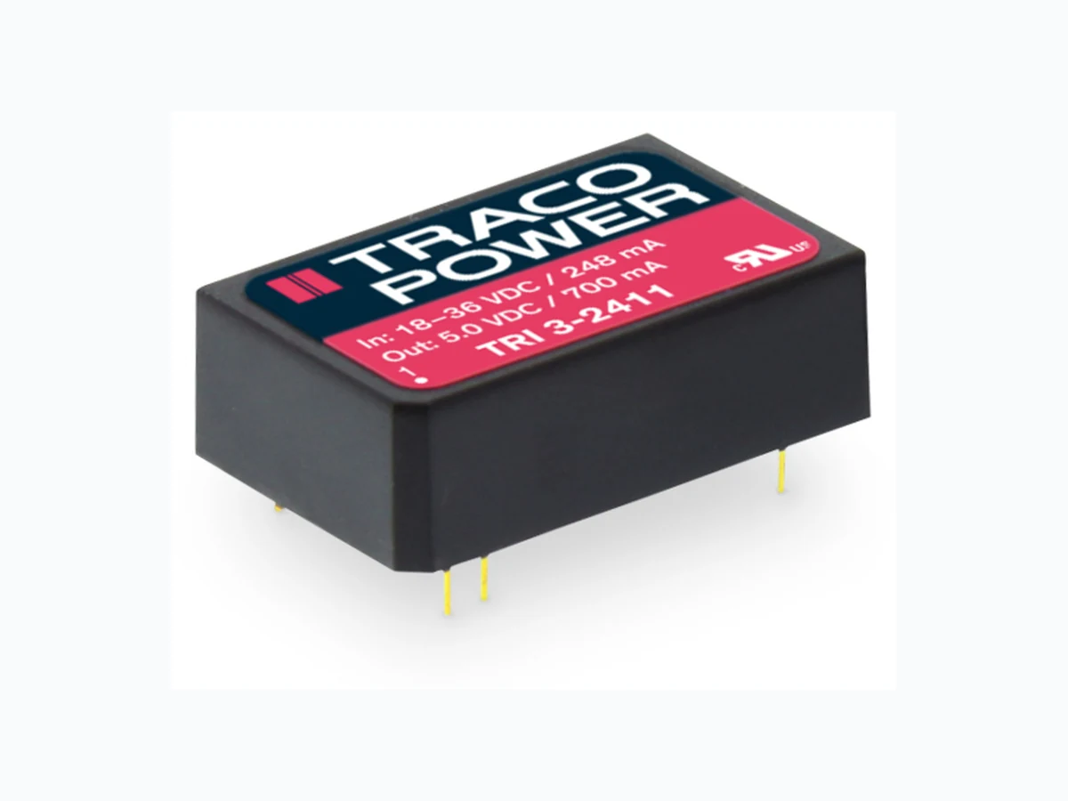
TRI3 TRACOPOWER
Document overview
- PDF pages: 4
Technical content
Page 1
DC/DC Converter
- Reinforced I/O-isolation 5000 VAC rated for 1000 VAC working voltage
- Ultra-high isolation peak voltage 9000 VDC (1s)
- Common Mode Transient Immunity (dv/dt) 15 kV/µs
- Operating temperature range -40 to
UL 62368-1 IEC 62368-1
+90°C
The new TRI 3 is a high isolation, regulated 3.5 Watt DC/DC converter series
- Low no-load power consumption 96 –
which comes in a compact DIP-24 package. The core characteristic of the TRI
192 mW
3 series is a sophisticated reinforced isolation system which is able to withstand high test voltages (9000 VDC for 1s and 5000 VAC for 60s) and working
- Internal EN 55032 class A filter
voltages (1000 VACrms). Complementing this isolation characteristic is a high
- High efficiency up to 87%
Common Mode Transient Immunity of 15 kV/µs. The new design allows to fully integrate an EN 55032 class A filter and greatly reduces the no-load power
- 2:1 input voltage range: 4.5-9, 9-18,
consumption. High efficiencies up to 87% allow safe operation from –40°C to
18-36, 36-75 VDC
+90°C without derating. All models have a wide 2:1 input voltage range and precisely regulated, isolated output voltages. With the latest IT safety certifica-
- Protection against overload, overvoltage
tions (IEC/EN/UL 62368-1) the TRI 3 series is the perfect choice for many de-
and short circuit
manding applications in the industrial, transportation and instrumentation sec-
- 3-year product warranty
tors.
Models
| Order Code | Input Voltage Range | Output 1 Vnom Imax | Output 2 Vnom Imax | Efficiency typ. | ||
|---|---|---|---|---|---|---|
| TRI 3-0511 TRI 3-0512 TRI 3-0513 TRI 3-0515 TRI 3-0522 TRI 3-0523 | 4.5 - 9 VDC (5 VDC nom.) | 5 VDC 12 VDC 15 VDC 24 VDC +12 VDC +15 VDC | 700 mA 290 mA 235 mA 146 mA 145 mA 115 mA | –12 VDC –15 VDC | 145 mA 115 mA | 82 % 83 % 84 % 83 % 84 % 84 % |
| TRI 3-1211 TRI 3-1212 TRI 3-1213 TRI 3-1215 TRI 3-1222 TRI 3-1223 | 9 - 18 VDC (12 VDC nom.) | 5 VDC 12 VDC 15 VDC 24 VDC +12 VDC +15 VDC | 700 mA 290 mA 235 mA 146 mA 145 mA 115 mA | –12 VDC –15 VDC | 145 mA 115 mA | 82 % 86 % 87 % 86 % 87 % 87 % |
| TRI 3-2411 TRI 3-2412 TRI 3-2413 TRI 3-2415 TRI 3-2422 TRI 3-2423 | 18 - 36 VDC (24 VDC nom.) | 5 VDC 12 VDC 15 VDC 24 VDC +12 VDC +15 VDC | 700 mA 290 mA 235 mA 146 mA 145 mA 115 mA | –12 VDC –15 VDC | 145 mA 115 mA | 82 % 85 % 87 % 86 % 87 % 86 % |
| TRI 3-4811 TRI 3-4812 TRI 3-4813 TRI 3-4815 TRI 3-4822 TRI 3-4823 | 36 - 75 VDC (48 VDC nom.) | 5 VDC 12 VDC 15 VDC 24 VDC +12 VDC +15 VDC | 700 mA 290 mA 235 mA 146 mA 145 mA 115 mA | –12 VDC –15 VDC | 145 mA 115 mA | 82 % 85 % 85 % 83 % 84 % 84 % |
Page 1 / 4
Page 2
Input Specifications
Input Current
- At no load
- At full load
Surge Voltage
Under Voltage Lockout
Recommended Input Fuse
Input Filter
Output Specifications
Voltage Set Accuracy Regulation
- Input Variation (Vmin - Vmax)
- Load Variation (0 - 100%)
- Voltage Balance (symmetrical load) - Cross Regulation (25% / 100% asym. load)
Ripple and Noise
- 20 MHz Bandwidth
Capacitive Load
- single output
- dual output
Minimum Load Temperature Coefficient Start-up Time Short Circuit Protection Output Current Limitation Overvoltage Protection Transient Response
- Response Deviation - Response Time
Safety Specifications
Safety Standards
- IT / Multimedia Equipment
- Certification Documents
Pollution Degree Over Voltage Category
5 Vin models: 30 mA typ. 12 Vin models: 10 mA typ. 24 Vin models: 6 mA typ. 48 Vin models: 4 mA typ. 5 Vin models: 838 mA typ. 12 Vin models: 339 mA typ. 24 Vin models: 170 mA typ. 48 Vin models: 87 mA typ. 5 Vin models: 15 VDC max. (1 s max.) 12 Vin models: 25 VDC max. (1 s max.) 24 Vin models: 50 VDC max. (1 s max.) 48 Vin models: 100 VDC max. (1 s max.) 5 Vin models: 4 VDC typ. 12 Vin models: 8 VDC typ. 24 Vin models: 16 VDC typ. 48 Vin models: 34 VDC typ.
(The need of an external fuse has to be assessed in the final application.) Internal Pi-Type
±1% max.
single output models: 0.5% max. dual output models: 0.5% max. single output models: 0.5% max. dual output models: 0.5% max. (Output 1)
0.5% max. (Output 2)
dual output models: 2% max.
dual output models: 5% max.
70 mVp-p max. (w/ 1 µF MLCC)
5 Vout models: 750 µF max. 12 Vout models: 130 µF max. 15 Vout models: 100 µF max. 24 Vout models: 39 µF max. 12 / -12 Vout models: 75 / 75 µF max. 15 / -15 Vout models: 56 / 56 µF max.
Not required ±0.02 %/K max. 30 ms max. Continuous, Automatic recovery 150% typ. of Iout max. 125% typ. of Vout nom. 5% max. (75% to 100% Load Step) 300 µs typ. (75% to 100% Load Step)
EN 62368-1 IEC 62368-1 UL 62368-1 www.tracopower.com/overview/tri3 PD 2 OVC II
All specifications valid at nominal voltage, resistive full load and +25°C after warm-up time, unless otherwise stated.
Page 2 / 4
Page 3
EMC Specifications
EMI Emissions
- Conducted Emissions
- Radiated Emissions
EN 55032 class A (internal filter) EN 55032 class B (with external filter) FCC Part 15 class A (internal filter) EN 55032 class A (with external filter)
External filter proposal: www.tracopower.com/overview/tri3
EMS Immunity
- Electrostatic Discharge
- RF Electromagnetic Field - EFT (Burst) / Surge
EN 55024 (IT Equipment) Air: EN 61000-4-2, ±15 kV, perf. criteria A Contact: EN 61000-4-2, ±6 kV, perf. criteria A EN 61000-4-3, 10 V/m, perf. criteria A EN 61000-4-4, ±2 kV, perf. criteria A EN 61000-4-5, ±2 kV, perf. criteria A
Ext. input component: 5 Vin models: KY 1000 µF / 35 V // V10P45
- Conducted RF Disturbances - PF Magnetic Field
General Specifications
Relative Humidity Temperature Ranges
- Operating Temperature - Case Temperature - Storage Temperature
Power Derating
- High Temperature
12 Vin models: KY 560 µF / 50 V 24 Vin models: KY 470 µF / 50 V 48 Vin models: KY 330 µF / 100 V EN 61000-4-6, 10 Vrms, perf. criteria A Continuous: EN 61000-4-8, 100 A/m, perf. criteria A
95% max. (non condensing) –40°C to +96°C +105°C max. –40°C to +125°C 8.3 %/K above 90°C
See application note: www.tracopower.com/overview/tri3
Cooling System Altitude During Operation Switching Frequency Insulation System Working Voltage (rated) Isolation Test Voltage
- Input to Output, 60 s - Input to Output, 1 s
Isolation Resistance
- Input to Output, 500 VDC
Isolation Capacitance
- Input to Output, 100 kHz, 1 V
Common Mode Transient Immunity Reliability
- Calculated MTBF
Washing Process
Natural convection (20 LFM) 5'000 m max. 330 kHz typ. (PWM) Reinforced Insulation 1'000 VAC 5'000 VAC 9'000 VDC 10'000 MΩ min. 40 pF max. 15 kV/µs min.
5'815'000 h (MIL-HDBK-217F, ground benign) Allowed (hermetical product)
See Cleaning Guideline:
Housing Material Potting Material Pin Material Pin Foundation Plating Pin Surface Plating Housing Type Mounting Type Connection Type Footprint Type Soldering Profile
Weight
www.tracopower.com/info/cleaning.pdf Plastic (UL 94 V-0 rated) Silicone (UL 94 V-0 rated) Copper Alloy (C6801) Nickel (2 - 4 µm) Tin (3 - 5 µm), matte Plastic Case PCB Mount THD (Through-Hole Device) DIP24 Wave Soldering 260°C / 10 s max. 15.5 g
All specifications valid at nominal voltage, resistive full load and +25°C after warm-up time, unless otherwise stated.
Page 3 / 4
Page 4
Environmental Compliance
- REACH Declaration
- RoHS Declaration
Supporting Documents
Overview Link (for additional Documents)
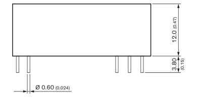
Outline Dimensions
www.tracopower.com/info/reach-declaration.pdf REACH SVHC list compliant REACH Annex XVII compliant www.tracopower.com/info/rohs-declaration.pdf Exemptions: 7a (RoHS exemptions refer to the component concentration only, not to the overall concentration in the product (O5A rule). The SCIP number is provided on request.)
www.tracopower.com/overview/tri3
| Pinout | ||
| Pin | Single Output | Dual Output |
| 1 | +Vin (Vcc) | +Vin (Vcc) |
| 11 | No pin | Common |
| 12 | –Vout | No pin |
| 13 | +Vout | –Vout |
| 15 | No pin | +Vout |
| 23 | –Vin (GND) | –Vin (GND) |
| 24 | –Vin (GND) | –Vin (GND) |
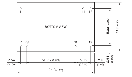
Dimensions in mm (inch) Tolerances: X.X ±0.5 (X.XX ±0.02) X.XX ±0.25 (X.XXX ±0.01) Pin Ø 0.6 ±0.05 (0.02 ±0.002)
© Copyright 2022 Traco Electronic AG
Specifications can be changed without notice.
Rev. November 30, 2022
Page 4 / 4