


 Download PDF
TR0636E-10026 HIROSE
Document overview
- PDF pages: 21
Technical content
Page 1
IT3 Thermal Cycling Test Report
(Solder type: Sn63 Pb37)

Approved. TY. ARAI June/23rd/2008
Checked . TM. MATSUO June/23rd /2008 Prepared. TY. TAKADA June/23rd /2008
Hirose Electric Co., Ltd.
- 1 -
Page 2
CONTENTS
1 OVERVIEW .................................................................................................................................3 2 TEST OBJECTIVES.......................................................................................................................3 3 THERMAL CYCLING TEST PROCEDURE ..........................................................................................4 4 TEST VEHICLES ..........................................................................................................................5 4.1 Connector Type...................................................................................................................5
4.2 Test Vehicle Configuration...................................................................................................5 4.3 Virgin or Reworked..............................................................................................................9 4.4 Test Variations ...................................................................................................................9 4.5 Number of Test Vehicles and Connectors ............................................................................9 5ASSEMBLY CONDITIONS.............................................................................................................10 5.1 Test Board Design Detail...................................................................................................10
5.2 Test Vehicle Assembly.......................................................................................................12 5.3 Rework .............................................................................................................................13 5.4 X-ray Inspection................................................................................................................14 5.5 Continuity Check...............................................................................................................15 6 THERMAL CYCLING TEST PROCESS.............................................................................................16
6.1 Preconditioning by Isothermal Aging..................................................................................16 6.2 Thermal Cycle Temperature Profile Requirement ..............................................................16 6.3 Thermal Cycling Test Execution.........................................................................................17 6.4 Measurement....................................................................................................................18 6.5 Failure Criteria ..................................................................................................................18 6.6 Identifying for Failure Connector(s) and Failure Point(s) ....................................................18
6.7 Rerouting with Jumper Wire ..............................................................................................18 6.8 Test Duration.....................................................................................................................18 6.9 Test Result........................................................................................................................19 7 SOLDER BALL SHEAR TEST........................................................................................................20 7.1 Measurement Method ......................................................................................................20
7.2 Failure Mode.....................................................................................................................20 7.3 Test Result........................................................................................................................20 8 REVISION RECORD....................................................................................................................21
9 Attachment _1 : 07-29834-R1 Thermal Cycling Test Report (Trace Laboratories,Inc.)
10 Attachment _2 : TR0636E-20027 BGA SHEARING TEST REPORT
11 Attachment _3: TR0636E-20033 CROSS SECTIONING REPORT
- 2 -
Page 3
1 OVERVIEW
The following test report is to be considered official documentation for results found during thermal cycle testing of the IT3 series BGA connector system. BGA connection is becoming a key technology for current and next generation high-speed transmission. It is crucial to perform accelerated life time testing to both simulate actual applications and prove BGA attachment reliability. All processes described herein, including test board design and thermal cycling test conditions, are based on and conform to IPC-9701.
All assembly and re-work processes were performed by Jabil Circuit, Inc. (San Jose, Ca., hereafter ‘Jabil’), and thermal cycling was performed by Trace Laboratories, Inc.(Chicago, Il.). This document includes all processes and test procedures followed, along with who and where they were performed.
2 TEST OBJECTIVES
The test samples and processes were prepared to simulate various applications that included: Both virgin and rework assemblies, connector configurations, and both single and multiple connector mounts.
- 3 -
Page 4
3 THERMAL CYCLING TEST PROCEDURE
| Jabil | Virgin assembly (5.2) Test samples (4.5) Eutectic X-ray inspection (5.4) Continuity check (5.5) Rework (5.3) Test samples (4.5) Eutectic X-ray inspection (5.4) Continuity check (5.5) Two combinations of assembled test samples [1 virgin, 1 reworked] | |
| Trace Labs | Thermal cycling test (6) Thermal cycling test start (6.3) Monitor the resistance increase to initial resistance (6.4) Yes (Failure): 20 % or more increase Five consecutive reading scans or more to the initial resistance is detected for five consecutive reading scans (6.5) Suspend thermal cycling test. Detect failure points. (6.6) No (Pass) Rerouting to skip the failure points with jumper wire (6.7) Resume Test NO (Failure): More than 50 % of all solder joints Failure points =< 50% (6.5) YES (Pass) Test duration (6.8) Terminate test 3500 cycles | Thermal Cycling Test Report (9) |
| Hirose & Jabil | Cross Section at BGA joints Solder ball sheer test (7) Jabil Hirose | Solder Ball Sheer Test Report (10) Cross Sectioning Report (11) |
- 4 -
Page 5
4 TEST VEHICLES
The following parameters were applied to simulate various manufacturing and connector usage situations.
4.1 Connector Type
Mezzanine Connector: Hirose IT3 series
Receptacle IT3M-300S-BGA(57)…Mounted on Mother Board
Receptacle
IT3D-300S-BGA(57)…Mounted on Daughter Card
Interposer Assembly
Interposer assembly IT3-300P-17H(03)…17 mm Stacking Height
IT3-300P-32H(03)…32 mm Stacking Height IT3 Connector
4.2 Test Vehicle Configuration
Boards were designed to a thickness of 3.3 mm (125 mils) per IPC-9701
4.2.1 Multiple Connector Mount
In many applications, multiple connectors are mounted on one daughter card which can create potential alignment issues and different stresses on solder joints. This test covers multiple connector mounting in various configurations.
| Config. 1 | Config. 2 | Config. 3 | Config. 4 | |
| Numbers of connectors / Daughter card | 1 | 2 | 2 | 4 |
| Remarks | Individual | X Direction(2 CN) | Y Direction(2CN) | Quad(4 CN) |
- 5 -
Page 6
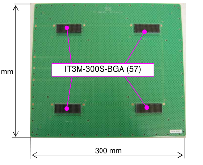
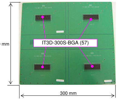
4.2.2 Test Board Examples IT3 mezzanine connectors were assembled to the board and tested . Each test board has four IT3 connectors
300 mm
Mother Board
300 mm
Daughter Card(Config.4)
- 6 -
Page 7
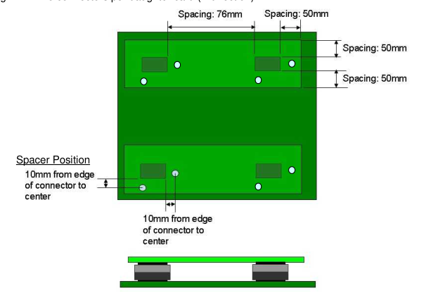
4.2.3 Test Board Configurations
Config. 1 ---One connector per daughter card
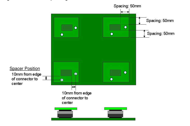
Config. 2 ---Two connectors per daughter card (X direction)
- 7 -
Page 8
Config. 3 ---Two connectors per daughter card (Y direction)
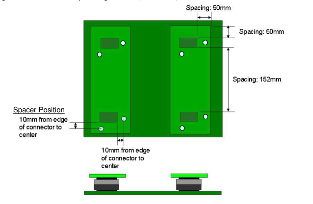
Config. 4 --- Four connectors per daughter card
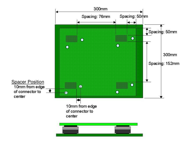
- 8 -
Page 9
4.3 Virgin or Reworked
To simulate the actual assembly process, both “Virgin” and “Reworked” board samples were tested. Assembly was done by Jabil, using industry standard assembly /rework equipment and processes.
| Virgin | Reworked | |
| Test Board | Virgin | Reuse after connector removal |
| Connector | Virgin | Virgin |
4.4 Type of Solder
| Virgin | Reworked | |
| Solder Ball on Connector | Eutectic | Eutectic |
| Solder Paste | Eutectic | Eutectic |
4.5 Number of Test Vehicles and Connectors
For 3.3mm (125 mil) thick test boards, the following number of connectors were used.
| Height | Config 1 | Config 2 | Config 3 | Config 4 | Total # of Connectors | |
| IT3-300S | 17H | 6/2 | 6/2 | 6/2 | 6/2 | 24/8 |
| 32H | 6/2 | 6/2 | 6/2 | 6/2 | 24/8 | |
| Totals | 12/4 | 12/4 | 12/4 | 12/4 | 48/16 | |
Note: 12/4 represents 12 Virgin and 4 Reworked
- 9 -
Page 10
5 ASSEMBLY CONDITIONS
5.1 Test Board Design Detail
Test Board Design Details per IPC-9701
| Item | Requirement | Remarks | |
| 1 | Thickness | 3.3mm (125 mils) per IPC-9701 | - |
| 2 | # of Metal Layers | 16 layers | - |
| 3 | Layer Structure | See Fig. 1 on the next page | - |
| 4 | PCB Material | High Tg FR-4 | IS-410/NP-150TL |
| 5 | Ground Layer | Remaining 70% copper mesh | Ground plane on even # layers |
| 6 | Signal Layer | Remaining 30% copper weave | Signal traces on odd # layers |
| 7 | Daisy Chain | On top layer only | - |
| 8 | Pad and Via | Pads for probing on the bottom layer through via | For failure analysis purposes, pads are connected by jumper cable to continue rest of the cycles if any failure is found. Simulate mechanical strength of actual PCBs with vias. |
| 9 | Surface Finish | High Tg OSP (Organic solderability preservative) | Passed IPC-S-804B solderability test IPC-TM-650 insulation resistance test IPC-6012(0.75%) warp and twist test |
| 10 | Pad Type | NSMD (Non-solder mask defined) | - |
| 11 | Copper Thickness | Outer layer: 35 microns Inner ground: 35 microns Inner signal: 18 microns | - |
| 12 | Trace Width | 200 microns (8 mils) | 150 microns (6 mils) minimum (IPC-9701) |
| 13 | # of Connectors | 10 connectors per board maximum | - |
Note: Test boards were designed to measure electrical continuity using the daisy chain circuit only. Vias were not connected to any specific signal or ground layers. Neither ground contacts nor ground layers are connected anywhere.
- 10 -
Page 11
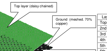
| Layer | Footprint type |
|---|---|
| Top | Daisy chain |
| 2nd | Ground layer |
| 3rd | Signal layer Type A |
| 4th | Ground layer |
| 5th | Signal layer Type B |
| 6th | Ground layer |
| 7th | Signal layer Type A |
| 8th | Ground layer |
| 9th | Signal layer Type B |
| 10th | Ground layer |
| 11th | Signal layer Type A |
| 12th | Ground layer |
| 13th | Signal layer Type B |
| 14th | Ground layer |
| 15th | Signal layer Type A |
| Bottom | Via test points |
Signal (weaved 30% copper)
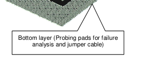
\* 16 Layers in Total
Fig. 1 PCB Layer Structure
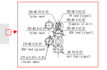
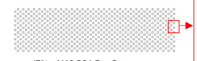
IT3\* – 300S-BGA Foot Pattern
Fig. 2 BGA Land Design
- 11 -
Page 12
5.2 Test Vehicle Assembly
Hirose provided assembly/rework process information, that was then adapted by Jabil to conform to industry standard practices. All connectors were assembled / reworked at Jabil.
5.2.1 Virgin Assembly Parameters
Process parameters followed for testing.
| Items | Requirements |
| Type of Reflow Equipment | Mass-reflow conveyor furnaces |
| Pre Conditioning | Dry package |
| Stencil | Thickness = 0.127 mm (0.005’’) Frame size X= 736.6 mm, Y= 736.6 mm (29’’ x 29’’) Open area ratio : 90% aperture size by area |
| Solder Ball Composition | Sn63 : Pb37 |
| Solder Paste Composition (Supplier Part Number) | Sn63 : Pb37 (Kester EP 256 no-clean Eutectic solder paste) |
| Process Parameters | DEK-265GSX Automatic screen printer Printing speed = 1’’/second Stencil snap off = 0 |
| Reflow Temperature Profile | See details on the next page. |
| Reflow Atmosphere | Nitrogen |
- 12 -
Page 13
5.3 Rework
“Rework” consists of a series of processes, such as removal of connector by using rework equipment (i.e., SRT), PCB cleaning and placement/reflow of a new connector using rework equipment.
5.3.1 Rework Parameters
| Items | Requirements |
| Type of Reflow Equipment | Hot air rework station |
| Stencil | Thickness = 0.127 mm (0.005’’) Open area ratio : 90% aperture size by area |
| Solder Ball Composition | Sn63 : Pb37 |
| Solder PasteComposition | Sn63 : Pb37 (Kester EP 256 no-clean Eutectic solder paste) |
| Rework Atomosphere | Nitrogen |
- 13 -
Page 14
5.4 X-ray Inspection Test Board Design Detail
X-ray inspection after assembly was conducted. All connectors passed the X-ray inspection before thermal cycling.
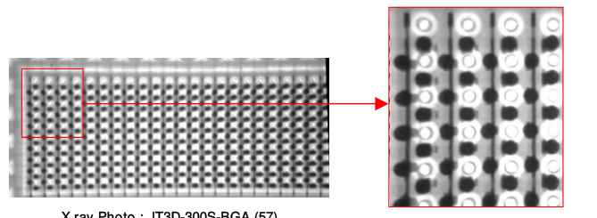
X ray Photo : IT3D-300S-BGA (57)
- 14 -
Page 15
5.5 Continuity Check
Final assembly, including mounting interposer assembly / daughter cards and board spacers, was performed to complete the daisy-chain circuit prior to performing the continuity check.
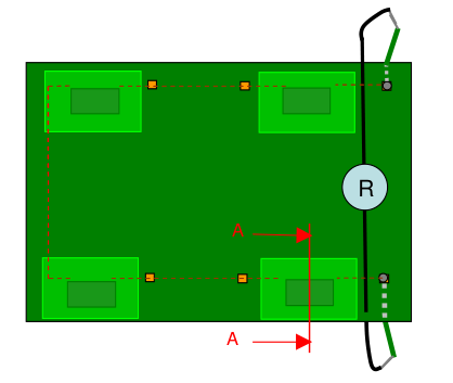
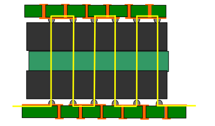
Cross section _ AA
Resistance Per Connector Chain
| IT3 Interposer Height | Resistance |
| 17 mm height | 25 to 29 |
| 32 mm height | 38 to 42 |
Unit : Ohm \* Resistance includes one connector assembly plus PCB trace.
- 15 -
Page 16
6 THERMAL CYCLING TEST PROCESS
Thermal cycling test performed conforms to IPC-9701 (JESD22-A-104-B).
6.1 Preconditioning by Isothermal Aging
Test specimens were subjected to an accelerated thermal aging (e.g. 24 hours at 100 qC (-0/+5 qC)) in air to simulate a reasonable use period and to accelerate such possible processes as solder gain, growth, intermetallic compound growth or oxidation. Test specimens were stored at room temperature following the artificial aging process and before commencing the thermal cycling test.
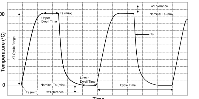
6.2 Thermal Cycle Chamber Profile
Dummy boards and connectors were employed to simulate expected thermal mass A minimum of 4 thermal couples near connectors on at least 2 boards Thermal cycle profile Tmax = 100 oC (+10 / 0 oC ) Tmin = 0 oC ( 0 / -10 oC) Ramp rate = Approximately 10 oC/min (10% to 90% of test temperature range) Dwell time = 5 to 10 min (Holding time of maximum and minimum temperature) 5 successful cycles were performed before commencing test.
100
Time
- 16 -
Page 17
6.3 Thermal Cycling Test Execution
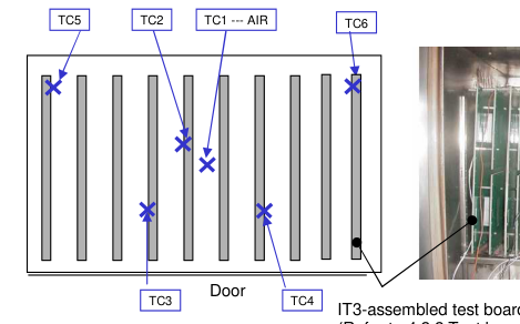
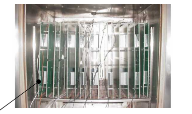
(Refer to 4.2.2 Test board example for test board details.)
Thermocouple Locations
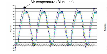
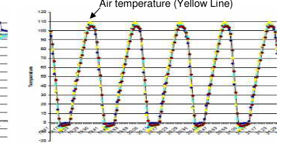
Chamber_2 TL 745
Chamber_1 TL 544
Measured Thermal Cycle Profile
- 17 -
Page 18
6.4 Measurement
Chamber temperature profile was continuously monitored and recorded during the test. Electrical resistance was monitored and recorded continuously. Maximum scan interval of all chains was one minute during test.
6.5 Failure Criteria
Failure was claimed when a 20% resistance increase to initial resistance was monitored for five consecutive reading scans. Failure points could not exceed 50 %.
6.6 Identifying Failed Connector(s) and Failure Point(s)
Failed connectors or failed points were identified by probing connector and specific test points and daisy chain test points located on the bottom of all test boards. Failure point(s) and number of cycles were recorded, when failure(s) occurred.
6.7 Rerouting with Jumper Wire
Once failure and location was detected, rerouting of the effected area was required. Jumper wires (AWG32, 60mm in length, pre-stripped and tinned) provided by Hirose were inserted approximately 2 mm into the appropriate through-holes and then soldered to complete the bypass.
6.8 Test Duration
3500 cycles
- 18 -
Page 19
6.9 Test Result
See attached document "07-29834-R1 PRINTED CIRCUIT BOARDS TEMPERATURE CYCLE" prepared by Trace Laboratories, Inc. for more details.
No failure was observed up to 3,500 temperature cycles.
| Board # | Initial Resistance | Final Resistance | Failure cycle & Resistance | Configuration | Conn-1 | Conn-2 | Conn-3 | Conn-4 |
| MB-001 | 40.9 | 40.1 | No failure | Config-1 | Virgin | Virgin | Virgin | Virgin |
| MB-002 | 26.5 | 25.8 | No failure | Config-1 | Virgin | Virgin | Virgin | Virgin |
| MB-003 | 40.2 | 39.7 | No failure | Config-2 | Virgin | Virgin | Virgin | Virgin |
| MB-004 | 26.0 | 25.6 | No failure | Config-2 | Virgin | Virgin | Virgin | Virgin |
| MB-005 | 39.9 | 39.6 | No failure | Config-3 | Virgin | Virgin | Virgin | Virgin |
| MB-006 | 25.7 | 25.2 | No failure | Config-3 | Virgin | Virgin | Virgin | Virgin |
| MB-007 | 40.2 | 39.8 | No failure | Config-4 | Virgin | Virgin | Virgin | Virgin |
| MB-008 | 26.5 | 26.1 | No failure | Config-4 | Virgin | Virgin | Virgin | Virgin |
| MB-009 | 41.1 | 40.1 | No failure | Config-1 | Virgin | Virgin | Reworked | Reworked |
| MB-010 | 27.5 | 26.5 | No failure | Config-1 | Virgin | Virgin | Reworked | Reworked |
| MB-011 | 41.0 | 40.4 | No failure | Config-2 | Virgin | Virgin | Reworked | Reworked |
| MB-012 | 26.0 | 26.6 | No failure | Config-2 | Virgin | Virgin | Reworked | Reworked |
| MB-013 | 39.8 | 41.1 | No failure | Config-3 | Reworked | Virgin | Virgin | Reworked |
| MB-014 | 26.9 | 27.5 | No failure | Config-3 | Reworked | Virgin | Virgin | Reworked |
| MB-015 | 40.6 | 41.5 | No failure | Config-4 | Reworked | Virgin | Virgin | Reworked |
| MB-016 | 26.4 | 26.9 | No failure | Config-4 | Reworked | Virgin | Virgin | Reworked |
Unit:ohm
Measurement Result
- 19 -
Page 20
7 SOLDER BALL SHEAR TEST
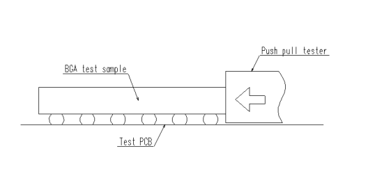
Ball shear qualification conforms to IPC-9701. The minimum shear force is defined as the mean minus 3 sigma, for a minimum of three connectors
7.1 Measurement Method
Force is applied to the edge of the connector so that the balls receive the shearing force. The height of shearing tool should exceed the height of the connector surface of 50μm minimum. Test speed: 500 micrometer / second
7.2 Failure Mode
The failure mode for the sheared balls is defined as either a bulk solder failure or copper pad lift-off. An intermetallic failure between contacts and balls is unacceptable.
7.3 Test Result
See the attachment "TR0636E-20027 : IT3D(M)-300S-BGA (57) BGA shearing force test report"
No intermetallic failure between contacts and balls was observed in both Initial and Post 3500 cycles specimens.
- 20 -
Page 21
- REVISION RECORD

- 21 -