

 Download PDF
TPI150A TRACOPOWER
Document overview
- PDF pages: 5
Technical content
Page 1
AC/DC Industrial Power Supply
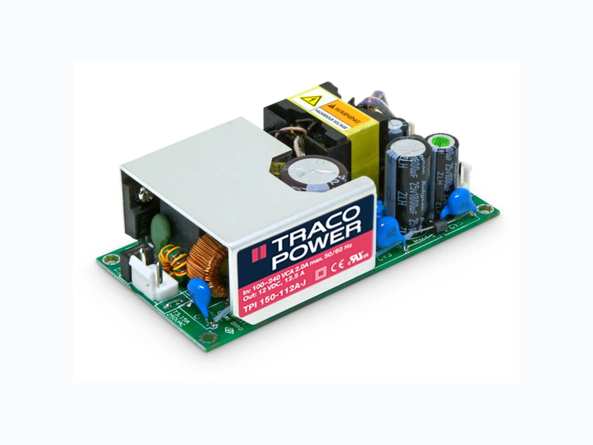
- Highest power density 150 W open frame power supply in 2” x 4” package
- I/O reinforced isolation 3000 VDC
- Ready to meet ErP directive, < 0.3 W no load power consumption
- Highest efficiency 91 - 92% across 10% - 100% load range
- Active power factor correction > 95
- Protection class II prepared
- Operating up to 5000 m altitude
- Adjustable output voltage
UL 62368-1 IEC 62368-1
- 3-year product warranty
The TPI 150A Series of 150 Watt AC/DC power supplies features a 3000 VDC I/O reinforced isolation. Excellent efficiency of up to 92% allows a high power density for the standard 2.0” x 4.0” packaging format. The full load operating temperature range is –40°C to +50°C while it goes up to +80°C with load derating. The power supplies are designed to meet the ErP directive (< 0.3 W no load power consumption). They come with an active power factor correction and the EMC characteristic is dedicated for applications in industrial and do- mestic fields. High reliability is provided by use of industrial quality grade components and an excellent thermal management. It makes the products an ideal
solution for any demanding industrial devices and space critical applications.
Models
| Order Code | Output Power max. | Output Voltage nom. (adjustable) | Output Current max. (Forced air cooling) | Output Current max. (Natural convection) | Efficiency typ. |
|---|---|---|---|---|---|
| TPI 150-112A-J TPI 150-115A-J TPI 150-124A-J TPI 150-128A-J TPI 150-136A-J TPI 150-148A-J | 150 W | 12 VDC (10.8 - 13.2 VDC) 15 VDC (13.5 - 16.5 VDC) 24 VDC (21.6 - 26.4 VDC) 28 VDC (25.2 - 30.8 VDC) 36 VDC (32.4 - 39.6 VDC) 48 VDC (43.2 - 52.8 VDC) | 12'500 mA 10'000 mA 6'250 mA 5'360 mA 4'170 mA 3'130 mA | 8'340 mA 7'340 mA 4'590 mA 3'930 mA 3'060 mA 2'090 mA | 91 % 92 % 92 % 92 % 92 % 92 % |
Page 1 / 5
Page 2
Input Specifications
Input Voltage
- AC Range
- DC Range
Input Frequency
Input Current
- Full Load & Vin = 230 VAC - Full Load & Vin = 115 VAC
Power Consumption
- No load & Vin = 230 VAC - No load & Vin = 115 VAC
Input Inrush Current
- At 230 VAC - At 115 VAC
Power Factor
- At 230 VAC - At 115 VAC
Input Protection Recommended Input Fuse
Output Specifications
Output Voltage Adjustment
Voltage Set Accuracy Regulation
- Input Variation (Vmin - Vmax) - Load Variation (0 - 100%)
Ripple and Noise (20 MHz Bandwidth)
Capacitive Load
Minimum Load Temperature Coefficient Hold-up Time
- At 230 VAC - At 115 VAC
Start-up Time
- At 230 VAC - At 115 VAC
Short Circuit Protection Output Current Limitation Overvoltage Protection Transient Response
- Response Deviation - Response Time
Operational Range: 85 - 264 VAC (Full Range) Rated Range: 100 - 240 VAC (Full Range) Operational Range: 120 - 370 VDC (Designed for, no certification) Polarity: +DC: L / –DC: N Operational Range: 47 - 440 Hz Certified: 50/60 Hz 800 mA max. 1'700 mA max. 300 mW max. (Ready to meet ErP directive) 300 mW max. 100 A max. 55 A max. 0.95 min. 0.95 min. T 3.15 A / 250 VAC (Internal Fuse in L & N) (The need of an external fuse has to be assessed in the final application.)
±10% (By trim potentiometer) Output power must not exceed rated power! ±1% max. 0.2% max. 0.5% max.
12 VDC model: 120 mVp-p typ. (w/ 1 µF X7R) 15 VDC model: 150 mVp-p typ. (w/ 1 µF X7R) 24 VDC model: 220 mVp-p typ. (w/ 1 µF X7R) 28 VDC model: 220 mVp-p typ. (w/ 1 µF X7R) 36 VDC model: 250 mVp-p typ. (w/ 1 µF X7R) 48 VDC model: 250 mVp-p typ. (w/ 0.1 µF X7R) 12 VDC model: 10'400 µF max. 15 VDC model: 6'600 µF max. 24 VDC model: 2'600 µF max. 28 VDC model: 1'900 µF max. 36 VDC model: 1'150 µF max. 48 VDC model: 650 µF max.
Not required ±0.02 %/K max. 16 ms min. 16 ms min. 1'000 ms max. 1'000 ms max. Continuous, Automatic recovery 115 - 150% of Iout max. 115 - 135% of Vout nom. 3% max. (50% to 75% Load Step) 500 µs typ. (50% to 75% Load Step)
All specifications valid at nominal voltage, resistive full load and +25°C after warm-up time, unless otherwise stated.
Page 2 / 5
Page 3
Safety Specifications
Safety Standards
- IT / Multimedia Equipment
- Certification Documents
Protection Class Pollution Degree Over Voltage Category
EMC Specifications
EMI Emissions
- Conducted Emissions
- Radiated Emissions
- Harmonic Current Emissions
- Voltage Fluctuations & Flicker
EMS Immunity
- Electrostatic Discharge
- RF Electromagnetic Field - EFT (Burst) / Surge
- Conducted RF Disturbances - PF Magnetic Field - Voltage Dips & Interruptions
General Specifications
Relative Humidity Temperature Ranges
- Operating Temperature - Storage Temperature
Power Derating
- High Temperature - Low Input Voltage
EN 60950-1 EN 62368-1 IEC 60950-1 IEC 62368-1 UL 60950-1 UL 62368-1 www.tracopower.com/overview/tpi150a Class I & II (Prepared): Reinforced Insulation PD 2 OVC II
EN 61000-6-4 (Generic Industrial) EN 55011 class B (internal filter) EN 55032 class B (internal filter) FCC Part 15 class B (internal filter) EN 55011 class A (internal filter) EN 55032 class A (internal filter) FCC Part 15 class A (internal filter) EN 61000-3-2, class A EN 61000-3-2, class D EN 61000-3-3 EN 55024 (IT Equipment) EN 55035 (Multimedia) Air: EN 61000-4-2, ±8 kV, perf. criteria A Contact: EN 61000-4-2, ±6 kV, perf. criteria A EN 61000-4-3, 20 V/m, perf. criteria A EN 61000-4-4, ±2 kV, perf. criteria A L to L: EN 61000-4-5, ±1 kV, perf. criteria A L to PE: EN 61000-4-5, ±2 kV, perf. criteria A EN 61000-4-6, 20 Vrms, perf. criteria A Continuous: EN 61000-4-8, 10 A/m, perf. criteria A
230 VAC / 50 Hz: EN 61000-4-11
30%, 25 periods, perf. criteria A >95%, 0.5 periods, perf. criteria A >95%, 250 periods, perf. criteria B
115 VAC / 60 Hz: EN 61000-4-11
30%, 25 periods, perf. criteria A >95%, 0.5 periods, perf. criteria A >95%, 250 periods, perf. criteria B
95% max. (non condensing) –40°C to +85°C –40°C to +85°C (-40°C startup: 80% load max. at Vin >100 VAC -40°C startup: 100% load max. at Vin >200 VAC) Depending on model 1.33 %/V below 100 VAC
See application note: www.tracopower.com/overview/tpi150a
Cooling System
- Option 1 - Option 2
Fan Power Source
- Characteristic - Output Voltage - Output Current
Forced air cooling (with external fan, 10 CFM) Natural convection (20 LFM) Variable fan speed (temperature regulated) 12 VDC 500 mA max.
All specifications valid at nominal voltage, resistive full load and +25°C after warm-up time, unless otherwise stated.
Page 3 / 5
Page 4
Altitude During Operation Switching Frequency Insulation System Working Voltage (rated) Isolation Test Voltage
- Input to Output, 60 s - Input to Case or PE, 60 s - Output to Case or PE, 60 s
Isolation Resistance
- Input to Output, 500 VDC
Leakage Current
- Touch Current
(at 264 VAC) Reliability
- Calculated MTBF
Environment
- Vibration
- Mechanical Shock
Housing Type Mounting Type Connection Type Weight Environmental Compliance - REACH Declaration
- RoHS Declaration
Supporting Documents
Overview Link (for additional Documents)
5'000 m max. 45 - 75 kHz (PWM QR) Reinforced Insulation 344 VAC 3'000 VAC 2'000 VAC 2'000 VAC 100 MΩ min. 300 µA max.
786'100 h (MIL-HDBK-217F, ground benign) IEC 60068-2-6 1 g, 3 axis, sine sweep, 10-55 Hz, 1 oct/min IEC 60068-2-27 10 g, 3 axis, half sine, 11 ms 20 g, 3 axis, 3 shocks Open Frame Chassis Mount Pin Connector 187 g www.tracopower.com/info/reach-declaration.pdf REACH SVHC list compliant REACH Annex XVII compliant www.tracopower.com/info/rohs-declaration.pdf Exemptions: 7a, 7c-I (RoHS exemptions refer to the component concentration only, not to the overall concentration in the product (O5A rule). The SCIP number is provided on request.)
www.tracopower.com/overview/tpi150a
All specifications valid at nominal voltage, resistive full load and +25°C after warm-up time, unless otherwise stated.
Page 4 / 5
Page 5
Outline Dimensions
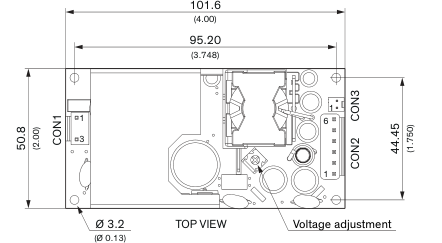
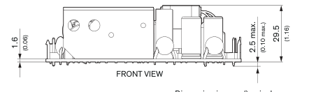
Dimension in mm, () = inch Tolerances: x.x ±0.50 (±0.02) x.xx ±0.25 (±0.01)
© Copyright 2023 Traco Electronic AG
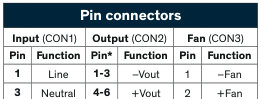
\*Terminal rated for 10 A max. (at higher current connection has to be split)
CON1: JST series mates with JST crimp terminal: SVH-21T-P1.1 and terminal housing: VHR-3N
CON2: JST series mates with JST crimp terminal: SVH-21T-P1.1 and terminal housing: VHR-6N
CON3: Molex series mates with Molex crimp terminals: 2759 and Molex housing: 22-01-1022
Specifications can be changed without notice.