

 Download PDF
TPI125A-J TRACOPOWER
Document overview
- PDF pages: 4
Technical content
Page 1
AC/DC Power Supply
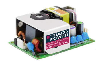
- 125 Watt open frame power supplies in a 3" x 2" package
- Compact and cost efficient design
- Peak power function up to 120%
- I/O reinforced isolation 3000 VAC
- Operating temperature range –40°C to +85°C
- No load input power <0.3W (acc. ErP directive)
- High efficiency up to 92%
- Internal EN 55032 class B filter
- Protection class II prepared
UL 62368-1 IEC 62368-1
- 3 year product warranty
The TPI 125A-J is a 125 Watt AC/DC open frame power supplies series with a 3000 VAC reinforced isolation system. Our TPI line specifically focuses on providing cost efficient industrial power supplies in compact designs. This series offers a peak power function which enables the unit to deliver up to 120% of the rated power for up to 10 seconds. Excellent efficiency of up to 92% allows a compact design and an operating temperature range (natural convection) of –40°C to +50°C without derating, while going up to +85°C with either load derating or forced cooling. They are designed to meet the ErP directive (< 0.3 W no load power consumption) and come with an EMC characteristics dedicat-
ed for applications in industrial/automation and test & measurement fields. High reliability is provided by use of industrial high-quality grade components and an excellent thermal management. It makes the TPI 125A-J an ideal solution for any demanding industrial devices or space critical applications.
Models
| Order Code | Output Power max. | Output Voltage nom. (adjustable) | Output Current max. (Forced air cooling) | Output Current max. (Natural convection) | Output Current peak | Efficiency typ. |
|---|---|---|---|---|---|---|
| TPI 125-112A-J TPI 125-115A-J TPI 125-124A-J TPI 125-136A-J TPI 125-148A-J | 125 W | 12 VDC (9.6 - 13.2 VDC) 15 VDC (12.0 - 16.5 VDC) 24 VDC (19.2 - 26.4 VDC) 36 VDC (28.8 - 39.6 VDC) 48 VDC (38.4 - 52.8 VDC) | 10'420 mA 8'340 mA 5'210 mA 3'480 mA 2'610 mA | 8'340 mA 6'670 mA 4'170 mA 2'780 mA 2'090 mA | 12'500 mA 10'000 mA 6'250 mA 4'167 mA 3'125 mA | 91 % 92 % 92 % 91 % 91 % |
Page 1 / 4
Page 2
Input Specifications
Input Voltage
- AC Range
- DC Range
Input Frequency
Input Current
- Full Load & Vin = 230 VAC - Full Load & Vin = 115 VAC
Power Consumption
- No load & Vin = 230 VAC - No load & Vin = 115 VAC
Input Inrush Current
- At 230 VAC - At 115 VAC
Power Factor
- At 230 VAC - At 115 VAC
Input Protection Recommended Input Fuse
Output Specifications
Output Voltage Adjustment
Voltage Set Accuracy Regulation
- Input Variation (Vmin - Vmax) - Load Variation (0 - 100%)
Boost Power
Ripple and Noise (20 MHz Bandwidth)
Capacitive Load
Minimum Load Temperature Coefficient Hold-up Time
- At 230 VAC - At 115 VAC
Start-up Time
- At 230 VAC - At 115 VAC
Short Circuit Protection Output Current Limitation Overvoltage Protection
Operational Range: 85 - 264 VAC (Full Range) Rated Range: 100 - 240 VAC (Full Range) Operational Range: 120 - 370 VDC (Designed for, no certification) Polarity: +DC: L / –DC: N Operational Range: 47 - 440 Hz Certified: 50/60 Hz 700 mA max. 1'800 mA max. 300 mW max. (Ready to meet ErP directive) 300 mW max. 100 A max. 60 A max. 0.95 min. (Active Power Factor Correction) 0.95 min. (Active Power Factor Correction) T 3.15 A / 250 VAC (Internal Fuse in L) (The need of an external fuse has to be assessed in the final application.)
–20% to +10% (For trim-down lower than -10% a minimum load of 0.25 W is required) (By trim potentiometer) Output power must not exceed rated power! ±1% max. 0.2% max. 0.5% max. Output Current peak: See model table 150 W max. peak power (≥ 130 VAC input) 140 W max. peak power (< 130 VAC input) Peak power time: 10 s max. Peak power duty cycle: 20% max. Average operation power: 55% of full load (detailed description see application note)
12 VDC model: 140 mVp-p typ. (w/ 10 µF, 25 V, MLCC) 15 VDC model: 150 mVp-p typ. (w/ 10 µF, 25 V, MLCC) 24 VDC model: 160 mVp-p typ. (w/ 1 µF, 50 V, MLCC) 36 VDC model: 190 mVp-p typ. (w/ 1 µF, 50 V, MLCC) 48 VDC model: 340 mVp-p typ. (w/ 0.1 µF, 100 V, MLCC) 12 VDC model: 8'700 µF max. 15 VDC model: 5'600 µF max. 24 VDC model: 2'200 µF max. 36 VDC model: 1'000 µF max. 48 VDC model: 550 µF max.
Not required ±0.02 %/K max. 40 ms min. 20 ms min. 730 ms max. 730 ms max. Continuous, Automatic recovery 120 - 160% of Iout max. 115 - 135% of Vout nom. (Latch off)
All specifications valid at nominal voltage, resistive full load and +25°C after warm-up time, unless otherwise stated.
Page 2 / 4
Page 3
Transient Response
- Response Deviation - Response Time
Safety Specifications
Safety Standards
- IT / Multimedia Equipment
- Certification Documents
Protection Class Pollution Degree Over Voltage Category
EMC Specifications
EMI Emissions
- Conducted Emissions
- Radiated Emissions
- Harmonic Current Emissions
- Voltage Fluctuations & Flicker
EMS Immunity
- Electrostatic Discharge
- RF Electromagnetic Field - EFT (Burst) / Surge
- Conducted RF Disturbances - PF Magnetic Field - Voltage Dips & Interruptions
General Specifications
Relative Humidity Temperature Ranges
- Operating Temperature - Storage Temperature
Power Derating
- High Temperature - Low Input Voltage
3% max. (50% to 75% Load Step at 2.5 A/µs) 500 µs typ. (50% to 75% Load Step at 2.5 A/µs)
EN 62368-1 IEC 62368-1 UL 62368-1 www.tracopower.com/overview/tpi125a-j Class I & II (Prepared): Reinforced Insulation PD 2 OVC II
EN 55032 class B (internal filter) FCC Part 15 class B (internal filter) EN 55032 class A (internal filter) FCC Part 15 class A (internal filter) EN 61000-3-2, class A EN 61000-3-2, class D EN 61000-3-3 EN 55024 (IT Equipment) EN 55035 (Multimedia) Air: EN 61000-4-2, ±8 kV, perf. criteria A Contact: EN 61000-4-2, ±6 kV, perf. criteria A EN 61000-4-3, 20 V/m, perf. criteria A EN 61000-4-4, ±2 kV, perf. criteria A L to L: EN 61000-4-5, ±1 kV, perf. criteria A L to PE: EN 61000-4-5, ±2 kV, perf. criteria A EN 61000-4-6, 20 Vrms, perf. criteria A Continuous: EN 61000-4-8, 10 A/m, perf. criteria A 230 VAC / 50 Hz: EN 61000-4-11 115 VAC / 60 Hz: EN 61000-4-11
95% max. (non condensing) –40°C to +85°C –40°C to +85°C (-40°C startup: 80% load max. at Vin >100 VAC -40°C startup: 100% load max. at Vin >200 VAC) Depending on model 1.33 %/V below 100 VAC
See application note: www.tracopower.com/overview/tpi125a-j
Cooling System
- Option 1 - Option 2
Altitude During Operation Switching Frequency Insulation System Working Voltage (rated) Isolation Test Voltage
- Input to Output, 60 s
Creepage
- Input to Output
Clearance
- Input to Output
Isolation Resistance
- Input to Output, 500 VDC
Leakage Current
- Touch Current
(at 264 VAC) Distance Through Isolation Reliability
- Calculated MTBF
Forced air cooling (with external fan, 400 LFM) Natural convection (20 LFM) 5'000 m max. 60 kHz typ. (PWM QR) Reinforced Insulation 527 VAC 4'000 VAC 8 mm min. 6.8 mm min. 100 MΩ min. 300 µA max.
0.4 mm 790'000 h (MIL-HDBK-217F, ground benign)
All specifications valid at nominal voltage, resistive full load and +25°C after warm-up time, unless otherwise stated.
Page 3 / 4
Page 4
Environment
- Vibration - Mechanical Shock
Housing Type Mounting Type Connection Type Weight Environmental Compliance - REACH Declaration
- RoHS Declaration
Supporting Documents
Overview Link (for additional Documents)
Outline Dimensions
77.2
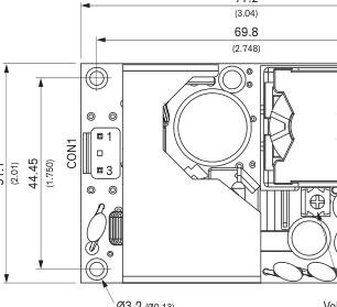
4
1
Voltage adj.
Ø3.2 (Ø0.13)
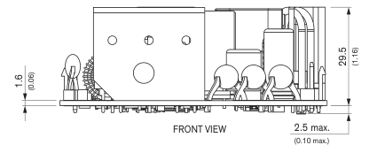
Dimensions in mm (inch) Tolerances: x.x ±0.5 (x.xx ±0.02) Tolerances: x.xx±0.25 (x.xxx ±0.01) Screw lock torque: Max. 0.49 Nm (5 kgfcm)
© Copyright 2023 Traco Electronic AG
IEC 60068-2-6 IEC 60068-2-27 Open Frame Chassis Mount Pin Connector 156 g www.tracopower.com/info/reach-declaration.pdf REACH SVHC list compliant REACH Annex XVII compliant www.tracopower.com/info/rohs-declaration.pdf Exemptions: 7a, 7c-I (RoHS exemptions refer to the component concentration only, not to the overall concentration in the product (O5A rule). The SCIP number is provided on request.)
www.tracopower.com/overview/tpi125a-j
| Pin connectors | |||
| Input (CON1) | Output (CON2) | ||
| Pin 1 | Function Line | Pin 1-2* | Function –Vout |
3
3-4\* Neutral
+Vout
Terminal rated for 10 A max. per pin.
CON1: JST series mates with JST crimp terminal: SVH-21T-P1.1 and terminal housing: VHR-3N
CON2: JST series mates with JST crimp terminal: SVH-21T-P1.1 and terminal housing: VHR-4N
Specifications can be changed without notice.
Rev. March 16, 2023 Page 4 / 4