

 Download PDF
TPC TRACOPOWER
Document overview
- PDF pages: 4
Technical content
Page 1
TPC Series, 30 to 120 Watt
CB
Features
Scheme
UL 60950-1 UL 508
◆ For industrial, office and residential
environments
◆ Meets European ErP directive (green mode),
<0.3 W no load power consumption
◆ High efficiency across full load range
◆ Compact plastic casing
◆ Reliable snap-on mounting on DIN-rails
or with wall mounting bracket (not included)
◆ Universal input 85–264 VAC, 47–63 Hz
◆ Models with 5, 12, 24 & 48 VDC output
◆ Output voltage adjustable
◆ Power good signal
◆ Low ripple and noise
◆ Overload and short-circuit protection
◆ Optional module for parallel and
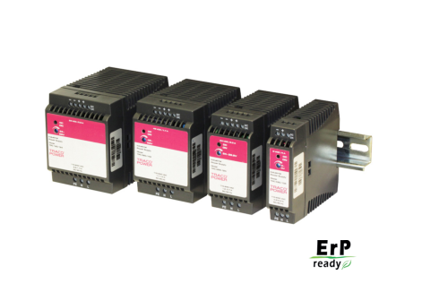
The TRACOPOWER TPC series is a family of lightweight DIN-rail power supplies with
redundant operation
an excellent price/performance ratio. They consume sparse standby power, and op
◆ Worldwide safety approval package
erate with high efficiency to comply with the requirements of the European Ecodesign
◆ 3-year product warranty
directive. They have universal input of 85-264VAC or 90-375VDC and are designed for class I operation in industrial and residential environments. With the optional active current sharing redundancy module, these power supplies provide a very reliable true redundant DC supply. For further details see page 3.
Models
| Order Code | Input Voltage Ranges | Output Power max. | Output Voltage nominal /adj. range | Output Current max. |
|---|---|---|---|---|
| TPC 030–105 TPC 030–112 TPC 030–124 TPC 030–148 | 85 – 264 VAC Universal Input 47/63 Hz 90 – 375 VDC | 20 W 26 W 30 W 30 W | 5.0 VDC /5.0–6.0 VDC 12 VDC /12–15 VDC 24 VDC /24–28.8 VDC 48 VDC /48–56 VDC | 4.0 A 2.2 A 1.25 A 0.6 A |
| TPC 055–112 TPC 055–124 TPC 055–148 | 42 W 55 W 55 W | 12 VDC / 12–15 VDC 24 VDC /24–28.8 VDC 48 VDC / 48–56 VDC | 3.5 A 2.3 A 1.15 A | |
| TPC 080–112 TPC 080–124 TPC 080–148 | 72 W 80 W 80 W | 12 VDC / 12–15 VDC 24 VDC /24–28.8 VDC 48 VDC /48–56 VDC | 6.0 A 3.3 A 1.7 A | |
| TPC 120–112 TPC 120–124 TPC 120–148 | 96 W 120 W 120 W | 12 VDC / 12–15 VDC 24 VDC /24–28.8 VDC 48 VDC /48–56 VDC | 8.0 A 5.0 A 2.5 A |
Page 1 of 4
Page 2
Input Specifications
Input voltage range
– AC nominal rated – AC range (designed for) – DC nominal rated – DC range (designed for)
Output derating
– at operation <100 VAC – at operation <130 VDC
110 – 240 VAC, 50-60 Hz 85 – 264 VAC, 47-63 Hz 130 – 300 VDC 90 – 375 VDC -2.5% /V -1.0% /VDC
TPC 030 and 055 models: < 0.3 W
Standby power consumption
TPC 080 and 120 models: < 0.5 W
Harmonic limits Recommended circuit breaker, characteristic C
Output Specifications
Output voltage adjustable range (potentiometer on frontpanel)
Regulation
– Input variation – Load variation (0–100 %)
Ripple and noise (20MHz bandwidth) Short circuit protection Overvoltage protection (% of max. adjustable voltage)
Power back immunity Start-up time Hold-up time (115 VAC / 230 VAC) Power OK signal
– trigger
EN 61000-3-2, Class A 6.0 – 16.0 A
5 VDC model: 5.0 – 6.0 VDC 12 VDC models: 12 – 15 VDC 24 VDC models: 24 – 28.8 VDC 48 VDC models: 48 – 56 VDC
0.5 % max.
5 VDC models: 0.75 % max. other models: 0.5 % max.
100 mVpk-pk max. <200 % of Iout nom.
5 VDC model: <180 % 12 VDC models: <170 % 24 VDC models: <160 % 48 VDC models: <107 %
125 % of nominal Vout 2 sec. max. min. 15 ms / min. 40 ms 80 – 95 %
– PNP open collector max. current 48 VDC models: 5 mA
General Specifications
Temperature ranges
– Operating – Storage (non operating)
Temperature derating Humidity (non condensing) Temperature coefficient Remote On/Off Efficiency (average at power consumption 25-100%)
Reliability, calculated MTBF at +25°C (according to IEC-1709)
Isolation voltage (60 s)
– Input / Output
Altitude during operation
other models: 10 mA
–25°C to +70°C max. –25°C to +85°C 2.5 %/K above 50°C 95 % rel. H max. 0.02 %/K 10 mA current source
TPC 030-105: 79 % other 30 Watt models: 84 % other models: 87 % TPC 030 models: >2.2 Mio h TPC 055 models: >1.7 Mio h TPC 080 models: >1.5 Mio h TPC 120 models: >1.3 Mio h
3000 VAC 2‘000 m max.
Page 2 of 4
Page 3
General Specifications
Safety standards
– CB test certificate
– SIQ type approved
– CSA certificate of compliance
– UL certificate of compliance – SIQ type approved
– Certification documents
Environmental compliance – Reach declaration document
– RoHS
EMC
– emissions – immunity
Class of protection Case protection Enclosure material Mounting
Supporting documents: www.tracopower.com/overview/tpc
TPC–REM240-24 Redundancy Module
IEC 60950-1:2005 2nd Ed, Am 1:2009 IEC/EN 61010-1, IEC 61010-2-201 EN 60950-1 :2006 + Am 1 :2010 + Am 11 :2009 + Am 12:2011 IEC/EN 61010-1, IEC/EN 61010-2-201 UL 60950-1-2nd Ed CSA 60950-1-07-2nd Ed UL 508, CSA C22.2 No.107.1-01 EN 60204-1:2006 + A1:2009, EN 61558-2-8:2010, EN 61558-2-16:2009, EN 50178:1997 www.tracopower.com/overview/tpc www.tracopower.com/info/reach-declaration.pdf RoHS directive 2011/65/EU IEC 61000-6-3 (residential environment) IEC 61000-6-2 (industrial environment) SEMI F47 class I (earth connection needed) IP 20 (IEC 60529) Makrolon 2405 (UL 94V-0 rated) DIN-rails as per EN 50022-35x15/7.5 (snap-on with self-locking spring) wall mounting bracket optional (not included)
| Order Code | Nominal Input Voltage | Max Power per Input | Output Voltage adjustable | Output Current max. |
|---|---|---|---|---|
| TPC–REM240–24 TPC–REM240–48 | 24 VDC 48 VDC | 120 W | 24 – 27 VDC 48 – 55 VDC | 10 A 5 A |
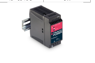
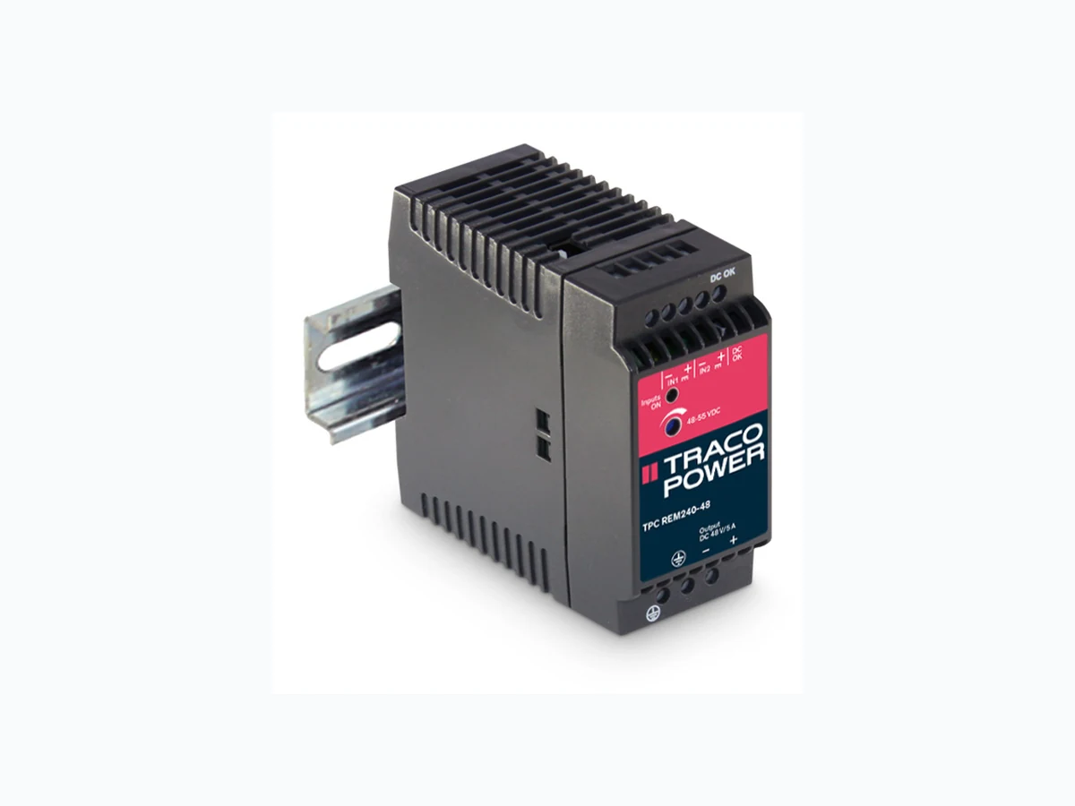
These modules are external units for operation with two TPC power supplies with output voltage of 24 VDC or 48 VDCand of same type and power. The modules allow to connect two outputs of TPC power supplies together in order to achieve a reliable DC supply. In normal operation the module achieves equal current share for both power supplies connected. During the redundancy operation, if one of the power supplies fails, the output power will be provided in full by the remain ing operating power supply. The redundancy of the DC system is monitored by a DC-OK signal.
Specifications
Operating temperature Electromagnetic compatibility
Dimensions
Connection Installation instructions
– installation document
–25°C to +70°C max. (with derating) in correspondence to connected units (no internal switching device) same as model TPC 055 (see page 4)
screw terminal block www.tracopower.com/overview/tpc
All specifications valid at nominal input voltage, full load and +25°C after warm-up time unless otherwise stated.
Page 3 of 4
Page 4
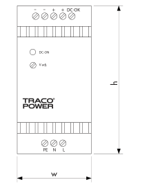
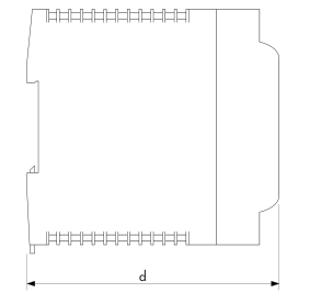
Case Dimensions
| Model | Width (W) | Heigth | Depth d | Weight |
| TPC 030 | 26.5 (1.04) | 90 (3.54) | 96.5 (3.80) | 160 g |
| TPC 055 | 45.0 (1.77) | 90 (3.54) | 96.5 (3.80) | 260 g |
| TPC-REM 240-24 | 45.0 (1.77 | 90 (3.54) | 96.5 (3.80) | 160 g |
| TPC 080 | 63.0 (2.48) | 90 (3.54) | 96.5 (3.80) | 360 g |
| TPC 120 | 72.0 (2.83) | 90 (3.54) | 110.0 (4.33) | 440 g |
Dimensions in [mm], ( ) = Inch Tolerances: ±0.5 mm (±0.02)
Wall Mounting Bracket (accessories not included)
| Order Code | For Models | Dimensions |
| TPC–WMK1 | TPC 030-xx | 26.0 x 35 x 7.5 |
| TPC–WMK2 | TPC 055-xx, TPC-REM 240–24 | 42.7 x 35 x 7.5 |
| TPC-WMK3 | TPC 080-xx | 60.7 x 35 x 7.5 |
| TPC-WMK4 | TPC 120-xx | 69.7 x 35 x 7.5 |
Snap-on bracket for wall mounting (black plastic)
Specifications can be changed without notice! Make sure you are using the latest documentation, downloadable at www.tracopower.com
Rev. February 1, 2021
www.tracopower.com
Page 4 of 4