
TP65H150BG4JSG_V01 RENESAS
Document overview
- Manufacturer or author: Provided By www.digicamel.com(free datasheet download site)
- PDF pages: 13
Technical content
Datasheet sections
- 1.1 Pin Assignments
- 1.2 Pin Descriptions
- 2.1 Absolute Maximum Ratings
- 2.2 Thermal Specifications
- 2.3 Electrical Specifications – Reverse Device
Features
■ Gen IV technology ■ JEDEC-qualified GaN technology ■ Dynamic RDS(on)eff production tested ■ Robust design, defined by:
- Transient over-voltage capability
- Operation with E-mode gate drivers without need for Zener protection ■ Negligible QRR ■ Reduced crossover loss ■ RoHS compliant and Halogen-free packaging
Applications
■ Consumer ■ Power adapters ■ Low power SMPS ■ Lighting Specifications VDS (V) 650 VDSS(TR)(V) maximum 800 RDS(on) (mΩ) maximum [1] 180 QOSS (nC) typical 35 QG (nC) typical 4.9 1. Dynamic RDS(on) (see Figure 17 and Figure 18)
1.1 Pin Assignments
Figure 1. Pin Assignments
1.2 Pin Descriptions
R07DS1671EU0402 Rev.4.02 Feb 9, 2026 Page 4 2. Specifications
2.1 Absolute Maximum Ratings
Tc = 25°C unless otherwise stated. Caution: Do not operate at or near the maximum ratings listed for extended periods of time. Exposure to such conditions can adversely impact product reliability and result in failures not covered by warranty. Symbol Parameter Limit Value Unit VDSS Drain to source voltage (TJ = -55°C to 150°C) 650 V VDSS(TR) Transient drain to source voltage [1] 800 VGSS Gate to source voltage +10 PD Maximum power dissipation at TC = 25°C 83 W ID Continuous drain current at TC = 25°C 16 A Continuous drain current at TC = 100°C 10 A IDM Pulsed drain current (pulse width: 10µs) 55 A TJ Junction operating temperature -55 to +150 °C TS Storage temperature -55 to +150 °C TSOLD Reflow soldering temperature [2] 260 °C 1. In off-state, spike duration < 30µs, non-repetitive. 2. Reflow MSL3.
2.2 Thermal Specifications
Symbol Condition Typical Value Unit RΘJC Junction-to-case 1.5 °C/W RΘJA Junction-to-ambient [1] 50 1. Device on one layer epoxy PCB for source connection (vertical and without air stream cooling, with 6cm2 copper area and 70µm thickness).
R07DS1671EU0402 Rev.4.02 Feb 9, 2026 Page 5 Electrical Specifications – Forward Device TJ = 25°C unless otherwise stated. Symbol Parameter Test Conditions Minimum Typical Maximum Unit VDSS(BL) Maximum drain-source voltage VGS = 0V 650 - - V VGS(th) Gate threshold voltage VDS = VGS, ID = 0.5mA 2 2.4 2.8 V ΔVGS(th)/TJ Gate threshold voltage temperature coefficient - -5.8 - mV/°C RDS(on)eff Drain-source on-resistance [1] VGS = 6V, ID = 10A, TJ = 25°C - 150 180 mΩ VGS = 6V, ID = 10A, TJ = 150°C - 307 - IDSS Drain-to-source leakage current VDS = 650V, VGS = 0V, TJ = 25°C - 2.5 25 µA VDS = 650V, VGS = 0V, TJ = 150°C - 10 - IGSS Gate-to-source forward leakage current VGS = 10V - - 100 nA Gate-to-source reverse leakage current VGS = -10V - - -100 CISS Input capacitance VGS = 0V, VDS = 400V, f = 1MHz - 400 - pF COSS Output capacitance - 37 - CRSS Reverse transfer capacitance - 1.2 - CO(er) Output capacitance, energy related [2] VGS = 0V, VDS = 0V to 400V - 50 - pF CO(tr) Output capacitance, time related [3] - 88 - QG Total gate charge VDS = 400V, VGS = 0V to 6V, ID = 10A - 4.9 - nC QGS Gate-source charge - 1.6 - QGD Gate-drain charge - 0.8 - QOSS Output charge VGS = 0V, VDS = 0V to 400V - 35 - nC tD(on) Turn-on delay VDS = 400V, VGS = 0V to 6V, ID = 10A, RG = 65Ω, ZFB = 330Ω at 100MHz (see Figure 15) - 24 - ns tR Rise time - 3.2 - tD(off) Turn-off delay - 22 - tF Fall time - 4 - 1. Dynamic RDS(on), 100% tested; see Figure 17 and Figure 18 for conditions. 2. Equivalent capacitance to give same stored energy from 0V to 400V. 3. Equivalent capacitance to give same charging time from 0V to 400V.
R07DS1671EU0402 Rev.4.02 Feb 9, 2026 Page 6
2.3 Electrical Specifications – Reverse Device
TJ = 25°C unless otherwise stated. Symbol Parameter Test Conditions Minimum Typical Maximum Unit IS Reverse current VGS = 0V, TC = 100°C, ≤ 25% duty cycle - - 10 A VSD Reverse voltage [1] VGS = 0V, IS = 8.5A - 1.7 - V VGS = 0V, IS = 4.5A - 1.2 - 1. Includes dynamic RDS(on) effect. Note: Reverse recovery charge is negligible, enabled by the LV Si FET technology
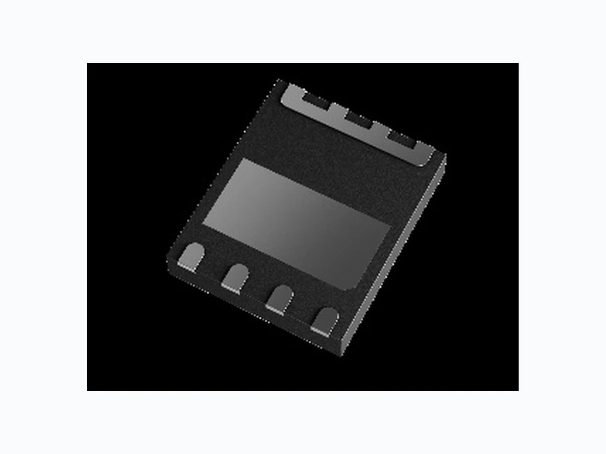
Figure 19. 5 × 6 mm PQFN Package Outline Drawing
R07DS1671EU0402 Rev.4.02 Feb 9, 2026 Page 12 6. Related Information All technical documents for Renesas GaN Power devices are accessible from the GaN Power Solutions page. 7. Ordering Information Part Number Package Description Package Configuration TP65H150BG4JSG -TR [1] 5 × 6 mm PQFN IP Source 1. “-TR” suffix refers to tape and reel. 8. Revision History Revision Date Description 4.02 Feb 9, 2026 Corrected device POD and pin assignments. 4.01 Jan 7, 2026 Corrected device schematic diagram. 4.00 Nov 25, 2025 Updated the document's formatting; no technical changes were completed.
3.03 Nov 7, 2023 Corrected the G label for Cascode Schematic Symbol
3.02 Aug 23, 2023
Added pin 1 to the package on front page Updated Transient condition statemen Updated IGSS Test Condition to VGS = 10V 4
3.01 Apr 2, 2023
Updated Rth Updated Qrr = 0 excludes Qoss
2.01 Mar 29, 2023 Final Datasheet
2.00 Jan 27, 2023 Preliminary Datasheet
1.00 Jun 17, 2022 Initial release.
TOYOSU FORESIA, 3-2-24 Toyosu, Koto-ku, Tokyo 135-0061, Japan www. renesas.com Contact Information For further information on a product, technology, the most up-to-date version of a document, or your nearest sales office, please visit www.renesas.com /contact-us/ . Trademarks Renesas and the Renesas logo are trademarks of Renesas Electronics Corporation. All trademarks and registered trademarks are the property of their respective owners. IMPORTANT NOTICE AND DISCLAIMER RENESAS ELECTRONICS CORPORATION AND ITS SU BSIDIARIES (“RENESAS”) PROVIDES TECHNICAL SPECIFICATIONS AND RELIABILITY DATA (INCLUDING DATASHEETS), DESIGN RESOURCES (INCLUDING REFERENCE DESIGNS), APPLICATION OR OTHER DESIGN ADVICE, WEB TOOLS, SAFETY INFORMATION, AND OTHER RESOURCES “AS IS” AND WITH ALL FAULTS, AND DISCLAIMS ALL WARRANTIES, EXPRESS OR IMPLIED, INCLUDING, WITHOUT LIMITATION, ANY IMPLIED WARRANTIES OF MERCHANTABILITY, FITNESS FOR A PARTICULAR PURPOSE, OR NON-INFRINGEMENT OF THIRD-PARTY INTELLECTUAL PROPERTY RIGHTS. These resources are intended for developers who are designing with Renesas products. You are solely responsible for (1) selecting the appropriate products for your application, (2) designing, validating, and testing your application, and (3) ensuring your application meets applicabl e standards, and any other safety, security, or other requirements. These resources are subject to change without notice. Renesas grants you permission to use these resources only to develop an application that uses Renesas products. Other reproduction or use of these resour ces is strictly prohibited. No license is granted to any other Renesas intellectual property or to any third-party intellectual property. Renesas disclaims responsibility for, and you will fully indem nify Renesas and its representatives again st, any claims, damages, costs, losses, or liabilities arising from your use of these resources. Renesas' products are provided only subject to Renesas' Terms and Conditions of Sale or other applicable terms agreed to in writ ing. No use of any Renesas re sources expands or otherwise alters any applicable warranties or warranty disclaimers for these products. (Disclaimer Rev.1.01) © 2026 Renesas Electronics Corporation. All rights reserved.