

 Download PDF
SE-SERIES ETC1
Document overview
- PDF pages: 5
Technical content
Page 1
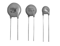
When the surge energy much higher than the rated maximum energy is applied to the varistors, it may blow up and catch fire. Our newly developed TNR SE series is to prevent from being caught fire even very high surge energy is applied. Thus electric appliance using our TNR SE series can be much safer.
?FEATURES
@Newly developed non-flammable material (Harogen Free) is used for outer coating. @The new outer coating will meet UL flammability test. @At the over voltage test, the new material shall deter burning caused by the high temperature, arc and the large surge current when TNR shall blow up. @General specifications are same as that of V series, large surge capability TNR.
?APPLICATIONS
@Protection for semiconductors from over voltage. @Protection for electronic instruments from lightning surge. @Absorption of on-off surge from motors and relays.
Operating Temperature Range: -40K+85C Storage Temperature Range: -50K+125C
?PART NUMBERING SYSTEM
TNR
SE
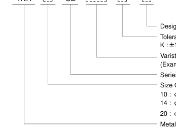
K : P10%
Size Code Design Code Tolerance of Varistor Voltage
Varistor Voltage (Example. 221=220V(=22B101) Series Name
10 : F10mm element diameter 14 : F14mm element diameter 20 : F20mm element diameter Metal Oxide Varistor "TNR"
(1/5)
Page 2
?RATINGS AND CHARACTERISTICS
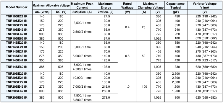
?DIMENSIONS [mm]
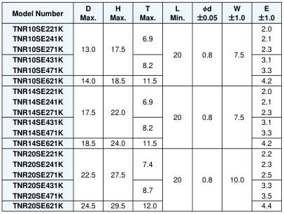
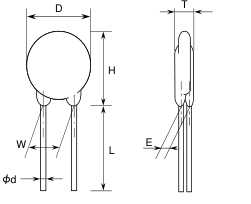
(2/5)
Page 3
?V-I CURVE
V-I characteristics is same as that of V series.
Please see V-I Curve of V series.
CROSS REFERENCE TABLE
| TNR SE SERIES | TNR V SERIES |
| TNR10SE221K TNR10SE241K TNR10SE271K TNR10SE431K TNR10SE471K TNR10SE621K | TNR10V221K TNR10V241K TNR10V271K TNR10V431K TNR10V471K TNR10V621K |
| TNR14SE221K TNR14SE241K TNR14SE271K TNR14SE431K TNR14SE471K TNR14SE621K | TNR14V221K TNR14V241K TNR14V271K TNR14V431K TNR14V471K TNR14V621K |
| TNR20SE221K TNR20SE241K TNR20SE271K TNR20SE431K TNR20SE471K TNR20SE621K | TNR20V221K TNR20V241K TNR20V271K TNR20V431K TNR20V471K TNR20V621K |
(3/5)
Page 4
?GENERAL SPECIFICATIONS
Operating Temperature Range: -40K+85C Storage Temperature Range: -50K+125C
| Item | Test Conditions | Specifications |
|---|---|---|
| Standard Test Condition | 20P5C, 65P20% RH unless specified. However, if it does not affect test result, the condition can be 20P15C, 65P20% RH also. | |
| Varistor Voltage | The voltage between the two terminals measured at 1mA DC is called Varistor Voltage. The measurement shall be made as fast as possible to aviod heat effection. | Satisfy the specification |
| Maximum Allowable Voltage | Maximum continuous AC voltage (50K60Hz AC) and maximum DC voltage which can be applided. | Satisfy the specification |
| Maximum Peak Surge Current | Maximum surge current (8/20MSec. pulse wave to be applied once, or twice, 2 minute apart) for varistor voltage change within P10% of the initial value. | Satisfy the specification |
| Energy Rating | Maximun energy (2mSec. square wave to be applied once) for varistor voltage change within P10% of the initial value. | Satisfy the specification |
| Rated Wattage | Maximum power (50K60Hz AC power to be applied for 1,000 hours at 85P2C) for varistor voltage change within P10% of the initial value. | Satisfy the specification |
| Maximum Clamping Voltage | Maximum voltage across varistor when 8/20MSec. rated current surge is applied. | Satisfy the specification |
| Capacitance | Varistor's capacitance at 1kHz, standard test condition. | For reference only. |
| Voltage Temparature Coefficient | V1mA at 85C – V1mA at 25C 1 B B100 (%/C) V1mA at 25C 60 V1mA : Actual Varistor Voltage | Within P0.05%/C |
| Insulation | Short circuit the two leads of varistor, and put the varistor body into lead balls (1.6mm diameter) leaving 2mm epoxy coating outside. Then, apply 2.5kVrms between the leads and the lead balls for 60P5 seconds. | The varistor shall withstand with no abnormality. |
?RELIABILITY CHARACTERISTICS
| Item | Test Conditions | Specifications |
|---|---|---|
| Heat Cycle | Subject varistor to the following tempmrature cycles. -40C for 30 minutes Normal room temperature for 10 minutes 85C for 30 minutes Normal room temperature for 10 minutes. This completes one cycle. The cycle shall be repeated 50 times total. After the cycles, the varistor shall be stored at normal room temperature for one hour. Then check the varistor voltage and the appearance. | DV1mA [P5% No appearance abnormality. |
| High Temperature Exposure | Store varistor at 125C for 1,000 hours. After that, store the varistor at normal room temperature for one hour. Then check the varistor voltage. | DV1mA [P5% |
| Humidity Resistivity | Store at 40C, 90K95% RH for 1,000 hours. After that, store the varistor at normal room temperature for one hour. Then cheek the varistor voltage. | DV1mA [P5% |
| High Temperature Operation | Apply maximum applied voltage to varistor at 85C for 1,000 hours. After that, store the varistor at normal room temperature for one hour. Then check the varistor voltage. | DV1mA [P10% |
(4/5)
Page 5
?MECHANICAL CHARACTERISTICS
| Item | Test Conditions | Specifications |
|---|---|---|
| Soldering Heat Resistivity | Store varistor at normal room temperature. Dip the varistor leads to solder, at 350P10C for 3P 1 seconds, up to 2.0K2.5 mm from the varistor body. After that, store the varistor at 0 normal room temperature for 30 miniutes, and measure the varistor voltage. | DV1mA [P5% Vc : Actual varistor voltage No mechanical damages |
| Solderability | Dip varistor leads to methanol solutin (JIS K 1501, about 25%) of rosin (JIS Z 5902) for 5K10 seconds. Then, dip the lead to solder (JIS Z 3282 H60A or H63A) at 225K240C, up to 2.0K 2.5mm from the varistor body for 5P0.5 seconds. Then, check the solderability. | At least, 95% of the surface dipped to solder shall be coverd by new solder. |
| Lead Pull Strength | Fix varistor body, and suspend specified weight toward direction of lead axis. Lead diameter Force F0.6mm, F0.8mm 10 N | No abnormality such as disconnection. DV1mA [P5% |
| Lead Bend Strength | The varistor shall be secured with its terminal kept vertical and the force specified below shall be applied in the axial direction. The terminal shall gradually be bend by 90 in one direction then back to original position. The damage of the terminal shall be visually examined. Lead diameter Force F0.6mm, F0.8mm 2.5 N | No remarkable damage as remarkable the inner ceramic element or terminal open. |
| Vibration Resistivity | Mount varistor body on vibrator, and conduct follwing vibration test. Peak-to-Peak amplitude : 1.5mm Vibration frequency range : 10HzK55Hz Sweeping time: Approximately one minute for 10Hz 55Hz 10Hz Direction and duration of vibration : Three directions of X, Y and Z. Two hours each. Six hours total. | No remarkable appearance abnormality. DV1mA P5% |
| Flammability test | The varistor shall be subjected to 60 second applications of test flame. Burner : Bunsen gas burner 9000kcal / m3 Diameter of flame nozzle : F9.5 mm Position : The specimen shall be fixed horizontal. Point of application shall be approximately center of the specimen. | No catching fire, and no flaming drops. |
(5/5)