
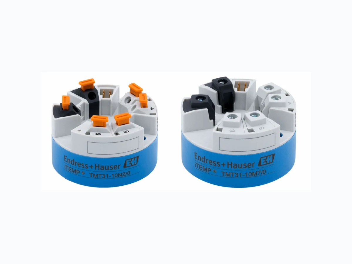
TI01613T EH
Document overview
- Manufacturer or author: Provided By www.digicamel.com(free datasheet download site)
- PDF pages: 12
Technical content
Form B (flat face) head transmitter with 4 to 20 mA analog output Application
- The iTEMP TMT31 is characterized by its reliability, long- term stability, high precision and diagnostic functions.
- For maximum safety and availability
- Installation in terminal head B Your benefits
- Diagnostics information according to NAMUR NE107
- Rapid no-tools wiring due to optional spring terminal technology
- Increased safety with Ex approvals
- High accuracy and flexibility with Callendar-van-Dusen equation Products Solutions Services Technical Information iTEMP TMT31 Temperature transmitter TI01613T/09/EN/01.21 71543230 2021-06-30
2 Endress+Hauser
Function and system design Measuring system 1 x RTD A0046627 1 Installed head transmitter - 1 x RTD wired directly Endress+Hauser offers a comprehensive range of industrial thermometers with resistance sensors. When combined with the temperature transmitter, these components form a complete measuring point for a wide range of applications in the industrial sector. The temperature transmitter is a 2-wire device with one measuring input and one analog output. It can be used for instrumentation in a Form B (flat face) terminal head as per DIN EN 50446. TMT31 DeviceCare/ FieldCare TXU10/FXA291 RN22/RN42 PLC A0046628 2 Device architecture for PC-programmable transmitter Standard diagnostic functions
- Cable open-circuit, short-circuit of sensor wires
- Incorrect wiring
- Internal device errors
- Overrange and underrange detection
- Device temperature overrange/underrange detection
- Low voltage detection Output simulation Simulation of the 4 to 20 mA output signal Input Measured variable Temperature (temperature-linear transmission behavior) Measuring rangeResistance thermometer (RTD) as per standard Designation α Measuring range limits Min. span IEC 60751:2008 Pt100 (1) Pt1000 (4) 0.003851 –200 to +850 °C (–328 to +1 562 °F) –200 to +250 °C (–328 to +482 °F) 10 K (18 °F) JIS C1604:1984 Pt100 (5) 0.003916 –200 to +510 °C (–328 to +950 °F) 10 K (18 °F)
4 Endress+Hauser
(RTD) as per standard Designation α Measuring range limits Min. span GOST 6651-94 Pt100 (9) 0.003910 –200 to +850 °C (–328 to +1 562 °F) 10 K (18 °F) - Pt100 (Callendar van Dusen) - The measuring range limits are specified by entering the limit values that depend on the coefficients A to C and R0. 10 K (18 °F)
- Type of connection: 2-wire, 3-wire or 4-wire connection, sensor current: ≤ 0.3 mA
- With 2-wire circuit, compensation of wire resistance possible (0 to 30 Ω)
- With 3-wire and 4-wire connection, sensor wire resistance up to max. 50 Ω per wire Output Output signal Analog output 4 to 20 mA, 20 to 4 mA (can be inverted) Failure information Failure information as per NAMUR NE43: Failure information is created if the measuring information is missing or not valid. The error with the highest priority is displayed. Underranging Linear drop from 4.0 to 3.8 mA Overranging Linear increase from 20.0 to 20.5 mA Failure e.g. sensor failure; sensor short-circuit ≤ 3.6 mA ("Low") or ≥ 21 mA ("High"), can be selected Linearization/transmission behavior Temperature-linear Filter 1st order digital filter: 0 to 120 s Network frequency filter: 50/60 Hz (cannot be adjusted) Switch-on delay ≤ 5 s, until the first valid measured value signal is present at the current output. While switch-on delay = Ia ≤ 3.8 mA Power supply Supply voltage Values for non-hazardous areas, protected against polarity reversal:
10 V ≤ Vcc ≤ 36 V (standard)
Values for hazardous areas, see Ex documentation. Current consumption 3.5 to 22.5 mA
3 Terminal assignment of head transmitter
1 RTD sensor input: 4-, 3- and 2-wire
2 Power supply
3 CDI interface
Terminal Choice of screw or push-in terminals for sensor and power supply cables: Terminal design Cable design Cable cross-section Screw terminals Rigid or flexible ≤ 1.5 mm² (16 AWG) Spring terminals 1) (Cable design, stripping length = min. 10 mm (0.39 in) Rigid or flexible 0.2 to 1.5 mm² (24 to 16 AWG) Flexible with wire end ferrules with/without plastic ferrule 0.25 to 1.5 mm² (24 to 16 AWG) 1) Wire end ferrules must be used with spring terminals and when using flexible cables with a cable cross- section of ≤ 0.3 mm². Performance characteristics Response time ≤ 0.5 s Reference operating conditions
- Calibration temperature: +25 °C ±3 K (77 °F ±5.4 °F)
- Supply voltage: 24 V DC
- 4-wire circuit for resistance adjustment Maximum measured error In accordance with DIN EN 60770 and the reference conditions specified above. The measured error data correspond to ±2 s (Gaussian distribution). The data include non-linearities and repeatability. MV = measured value LRV = lower range value of sensor Transmitter measured error Version Measured error (±) In entire measuring range 0.15 K or 0.07 % of span 1) Increased accuracy in limited measuring range, –50 to +250 °C (–58 to +482 °F) 0.1 K or 0.07 % of span 1) 1) whichever is higher The measured error data correspond to 2 s (Gaussian distribution)
6 Endress+Hauser
Operating influences The measured error data correspond to 2 s (Gaussian distribution). Operating influences: ambient temperature and supply voltage for resistance temperature detector (RTD) Designation Standard Ambient temperature: Influence (±) per 1 °C (1.8 °F) change Supply voltage: Influence (±) per V change 0 to +200 °C (+32 to +392 °F) Entire measuring range 0 to +200 °C (+32 to +392 °F) Entire measuring range Pt100 (1) IEC 60751:2008 Long-term drift (±) 1) after 1 year after 3 years after 5 years Based on measured value 1) whichever is higher Calculation of the maximum measured error of the analog value (current output): √(Measured error² + Influence of ambient temperature² + Influence of supply voltage²) Sensor adjustment Sensor-transmitter-matching To significantly improve the temperature measurement accuracy of RTD sensors, the device enables the following method: Callendar-Van-Dusen coefficients (Pt100 RTD assembly) The Callendar-Van-Dusen equation is described as: RT = R0[1+AT+BT²+C(T-100)T³] The coefficients A, B and C are used to match the sensor (platinum) and transmitter in order to improve the accuracy of the measuring system. The coefficients for a standard sensor are specified in IEC 751. If no standard sensor is available or if greater accuracy is required, the coefficients for each sensor can be determined specifically with the aid of sensor calibration. Sensor-transmitter-matching using the method explained above significantly improves the temperature measurement accuracy of the entire system. This is because the transmitter uses the specific data pertaining to the connected sensor to calculate the measured temperature, instead of using the standardized sensor curve data. 1-point adjustment (offset) Shifts the sensor value Current output adjustment Correction of the 4 and/or 20 mA current output value.
A Terminal head Form B (flat face) as per DIN EN 50446, direct installation on insert with cable entry (middle hole 7 mm (0.28 in)) B With DIN rail clip on DIN rail as per IEC 60715 (TH35) When installing the head transmitter in a terminal head form B (flat face), make sure there is sufficient space in the terminal head! Environment Ambient temperature –40 to +85 °C (–40 to +185 °F), Storage temperature –50 to +100 °C (–58 to +212 °F) Operating altitude Up to 4000 m (4374.5 yards) above sea level. Humidity • Condensation: Permitted
- Max. rel. humidity: 95 % as per IEC 60068-2-30 Climate class Climate class C1 according to IEC 60654-1 Degree of protection With screw terminals: IP 00, with spring terminals: IP 30. In the installed state, it depends on the terminal head or housing used for field mounting. Shock and vibration resistance Vibration resistance as per DNVGL-CG-0339 : 2015 and DIN EN 60068-2-27 8.6 to 150 Hz at 3g Shock resistance as per KTA 3505 (section 5.8.4 Shock test) Electromagnetic compatibility (EMC) CE conformity Electromagnetic compatibility in accordance with all the relevant requirements of the IEC/EN 61326 series and NAMUR Recommendation EMC (NE21). For details, refer to the Declaration of Conformity. Maximum measured error <1% of measuring range. Interference immunity as per IEC/EN 61326 series, industrial requirements
8 Endress+Hauser
Interference emission as per IEC/EN 61326 series (CISPR 11), Class B, group 1 equipment Measuring category Measuring category II as per IEC 61010-1. The measuring category is provided for measuring on power circuits that are directly connected electrically with the low-voltage network. Pollution degree Pollution degree 2 as per IEC 61010-1 Mechanical construction Design, dimensions Dimensions in mm (in) 26.5 /UNI23005 (0.2) B A A0047020 4 Version with screw terminals A Spring travel L ≥ 5 mm (not for US - M4 securing screws) B CDI interface for connecting a configuration tool 30 (1.18) A0036304 5 Version with spring terminals. Dimensions are identical to the version with screw terminals, apart from housing height. Weight 40 to 50 g (1.4 to 1.8 oz) Materials All the materials used are RoHS-compliant.
- Housing: polycarbonate (PC)
- Terminals:
- Screw terminals: nickel-plated brass
- Push-in terminals: tin-plated brass, contact springs 1.4310, 301 (AISI)
- Potting compound: SIL gel
Remote operation device-specific parameters are configured via the CDI interface (service interface) of the device. There are special configuration tools from different manufacturers available for this purpose. For more information, contact your Endress+Hauser sales representative. Write protection for device parameters Software: Write protection using password User role concept (password allocation) Certificates and approvals Current certificates and approvals for the product are available via the Product Configurator at www.endress.com. 1. Select the product using the filters and search field. 2. Open the product page. The Configuration button opens the Product Configurator. MTTF 418 years The mean time to failure (MTTF) denotes the theoretically expected time until the device fails during normal operation. The term MTTF is used for systems that cannot be repaired, e.g. temperature transmitters.
Ordering information
Detailed ordering information is available for your nearest sales organization 1. Click Corporate 2. Select the country 3. Click Products 4. Select the product using the filters and search field 5. Open the product page The Configuration button to the right of the product image opens the Product Configurator. Product Configurator - the tool for individual product configuration
- Up-to-the-minute configuration data
- Depending on the device: Direct input of measuring point-specific information such as measuring range or operating language
- Automatic verification of exclusion criteria
- Automatic creation of the order code and its breakdown in PDF or Excel output format
- Ability to order directly in the Endress+Hauser Online Shop Accessories Various accessories, which can be ordered with the device or subsequently from Endress+Hauser, are available for the device. Detailed information on the order code in question is available from your local Endress+Hauser sales center or on the product page of the Endress+Hauser website: www.endress.com. Device-specific accessories Adapter for DIN rail mounting, DIN rail clip as per IEC 60715 (TH35) without securing screws Standard - DIN mounting set (2 screws + springs, 4 lock washers and 1 CDI connector cover) US - M4 securing screws (2 M4 screws and 1 CDI connector cover)
10 Endress+Hauser
Commubox FXA291 Connects Endress+Hauser field devices with a CDI interface (= Endress+Hauser Common Data Interface) and the USB port of a computer or laptop. For details, see Technical Information TI405C/07 Configuration kit TXU10 Configuration kit for PC-programmable transmitters – FDT/DTM-based plant asset management tool, FieldCare/DeviceCare and interface cable (4-pin plug-in connector) for PC with USB port. Service-specific accessories Accessories Description Applicator Software for selecting and sizing Endress+Hauser measuring devices:
- Calculation of all the necessary data for identifying the optimum measuring device: e.g. pressure loss, accuracy or process connections.
- Graphic illustration of the calculation results Administration, documentation and access to all project-related data and parameters over the entire life cycle of a project. Applicator is available: Via the Internet: https://portal.endress.com/webapp/applicator Accessories Description Configurator Product Configurator - the tool for individual product configuration
- Up-to-the-minute configuration data
- Depending on the device: Direct input of measuring point-specific information such as measuring range or operating language
- Automatic verification of exclusion criteria
- Automatic creation of the order code and its breakdown in PDF or Excel output format
- Ability to order directly in the Endress+Hauser Online Shop The Configurator is available on the Endress+Hauser website at: www.endress.com -> Click "Corporate" -> Select your country -> Click "Products" -> Select the product using the filters and search field -> Open product page -> The "Configure" button to the right of the product image opens the Product Configurator. DeviceCare SFE100 Configuration tool for devices via fieldbus protocols and Endress+Hauser service protocols. DeviceCare is the tool developed by Endress+Hauser for the configuration of Endress+Hauser devices. All smart devices in a plant can be configured via a point- to-point or point-to-bus connection. The user-friendly menus enable transparent and intuitive access to the field devices. For details, see Operating Instructions BA00027S FieldCare SFE500 FDT-based plant asset management tool from Endress+Hauser. It can configure all smart field units in your system and helps you manage them. By using the status information, it is also a simple but effective way of checking their status and condition. For details, see Operating Instructions BA00027S and BA00065S
System components Accessories Description RN22/RN42 RN22: 1- or 2-channel active barrier for the separation of 0/4 to 20 mA standard signal circuits, optionally available as a signal doubler, 24 V DC. HART-transparent RN42: 1-channel active barrier with wide range power supply for the safe separation of 0/4 to 20 mA standard signal circuits, HART-transparent For details
- Technical Information RN22 -> TI01515K
- Technical Information RN42 -> TI01584K RIA15 Process display, digital, loop-powered digital display unit for 4 to 20 mA circuits For details, see Technical Information TI01043K RNB22 System power supply with wide range input 100 to 240 VAC / 110 to 250 VDC Primary switched mode power supply, 1-phase, output 24 VDC / 2.5 A For details, see Technical Information TI01585K Documentation
- Operating Instructions ’iTEMP TMT31' with analog output 4 to 20 mA (BA02157T) and associated printed copy of Brief Operating Instructions 'iTEMP TMT31' (KA01540T)
- Description of Device Parameters (GP01182T)
- Supplementary ATEX (XA02682T) and CSA (XA02683T) documentation
www.addresses.endress.com *71543230* 71543230