


 Download PDF
TLF0602-820Y RFE
Document overview
- PDF pages: 2
Technical content
Page 1
SURFACE MOUNT TRANSFORMERS TLF Series: Line Filter (Common Mode Choke)
FEATURES
- Miniature surface mount component •For EMI countermeasures at
- High performance ferrite with superior signal lines of microcomputer,
frequency characteristics
peripheral devices, etc.
ELECTRICAL CHARACTERISTICS
| Part Number | Inductance (uH) 0.1V, 1KHZ | DC Resistance (One Line) ( mW ) | Rated Current ( mA ) | Insulation Resistance (mW) /100VDC | Style | |||
|---|---|---|---|---|---|---|---|---|
| L ONE LINE | L1 - L2 L3 - L4 | L1, L2 | L1 - L2 | |||||
| TLF0602-820Y | 82±50% | 4 max | 200 max. | 300 | 10 max. | A | ||
| TLF0602-181Y | 180±50% | 8 max | 250 max | 300 | 10 max. | A | ||
| TLF0602-331Y | 330±50% | 10 max | 300 max. | 300 | 10 max. | A | ||
| Hi-Pot test (N1-N2): 250VAC / 60Hz, 3mA, 1 minute | ||||||||
| TLF0905-100Y | 10±30% | 1 max | 90 max | 1500 | 10 max. | A | ||
| TLF0905-470Y | 47±30% | 3 max | 255 max | 940 | 10 max | A | ||
| TLF0905-251Y | 250-+ 35 00 %% | 30 max | 110 max | 1430 | 10 max. | A | ||
| TLF0905-501Y | 500+50% | 30 max | 150 max | 1200 | 10 max. | A | ||
| TLF0905-102Y | -30% 1000-+ 35 00 %% | 35 max | 300 max | 850 | 10 max. | A | ||
| TLF0905-202Y | 2000-+ 35 00 %% | 55 max | 470 max | 680 | 10 max | A | ||
| Hi-Pot test (N1-N2): 700VAC / 60Hz, 3mA, 1 minute | ||||||||
| TLF1306 - 350Y* | 35.0±35% | 4.0 max | 35 max | 2700 | 10 max. | B | ||
| TLF1306 - 600Y* | 60.0±35% | 5.0 max | 65 max | 2000 | 10 max. | B | ||
| TLF1306 - 101Y** | 100±35% | 15 max. | 100 max. | 700 | 10 max. | C | ||
| TLF1306 - 251Y** | 250±35% | 25 max. | 150 max. | 600 | 10 max. | C | ||
| TLF1306 - 501Y** | 500±35% | 35 max. | 200 max. | 500 | 10 max. | C | ||
| TLF1306 - 102Y** | 1000±35% | 45 max. | 300 max. | 400 | 10 max. | C | ||
| TLF1306 - 332Y** | 3300±35% | 85 max. | 510 max. | 300 | 10 max. | B | ||
| Hi-Pot Test: 700 Vac/60 Hz, 3mA, 1 minute *Temperature Rise: 45°C max. at rated current **Temperature Rise: 20°C max at rated current. | Note: L, L1, L2: Inductance rating of each winding L1-L2, L3-L4 Max difference between windings. | |||||||
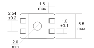
DIMENSIONS (mm)
SCHEMATIC DIAGRAMS
Type A
3
1
N2
N1
4
2
“•”: Polarity
Type B
4
1
N2
N1
5
8
“•”: Polarity
Type C
2
4
1
3
N2 N1
N2
N1
7 6
5
8
“•”: Polarity
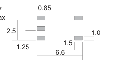
PC Board Pattern
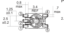
TLF0602 Size
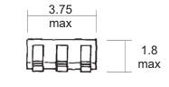
6.5 max
TLF0905 Size
PC Board Pattern
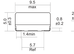
1.2
2.54
2.0 9.5
PC Board Pattern
TLF1306 Size
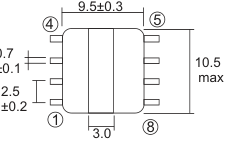
10.3 2.2
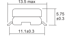
1.0
2.5
14.7
C4D01
RFE International • Tel:(949) 833-1988 • Fax:(949) 833-1788 • E-Mail Sales@rfeinc.com
REV 2001
Page 2
SURFACE MOUNT TRANSFORMERS TLF Series: Line Filter (Common Mode Choke)
IMPEDANCE vs FREQUENCY
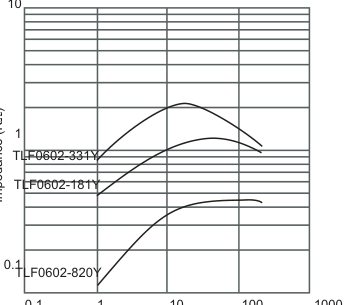
0.1 1 10 100 1000
Frequency (MHz)
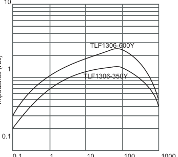
0.1 1 10 100 1000
Frequency (MHz)
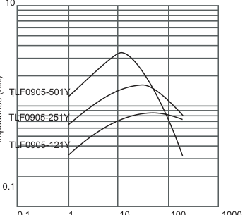
0.1 1 10 100 1000
Frequency (MHz)
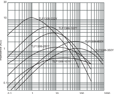
0.1 1 10 100 1000
Frequency (Mhz)
C4D01
RFE International • Tel:(949) 833-1988 • Fax:(949) 833-1788 • E-Mail Sales@rfeinc.com
REV 2001